A transformer winding is usually described by turns ratio, inductance and resistance. At higher frequencies another property becomes important: the capacitance between conductors that sit next to each other inside the same coil. Those conductors form many small capacitors distributed through the winding, and together they influence resonance, switching behaviour and how the part behaves in the circuit. The winding pattern is therefore not only a mechanical arrangement but an electrical decision.
This article keeps the discussion qualitative. It does not give formulas, target values or material constants, because those depend on the specific design and should come from the part specification and its own verification. The aim is to show which choices are available to the process engineer and which are fixed by the design.
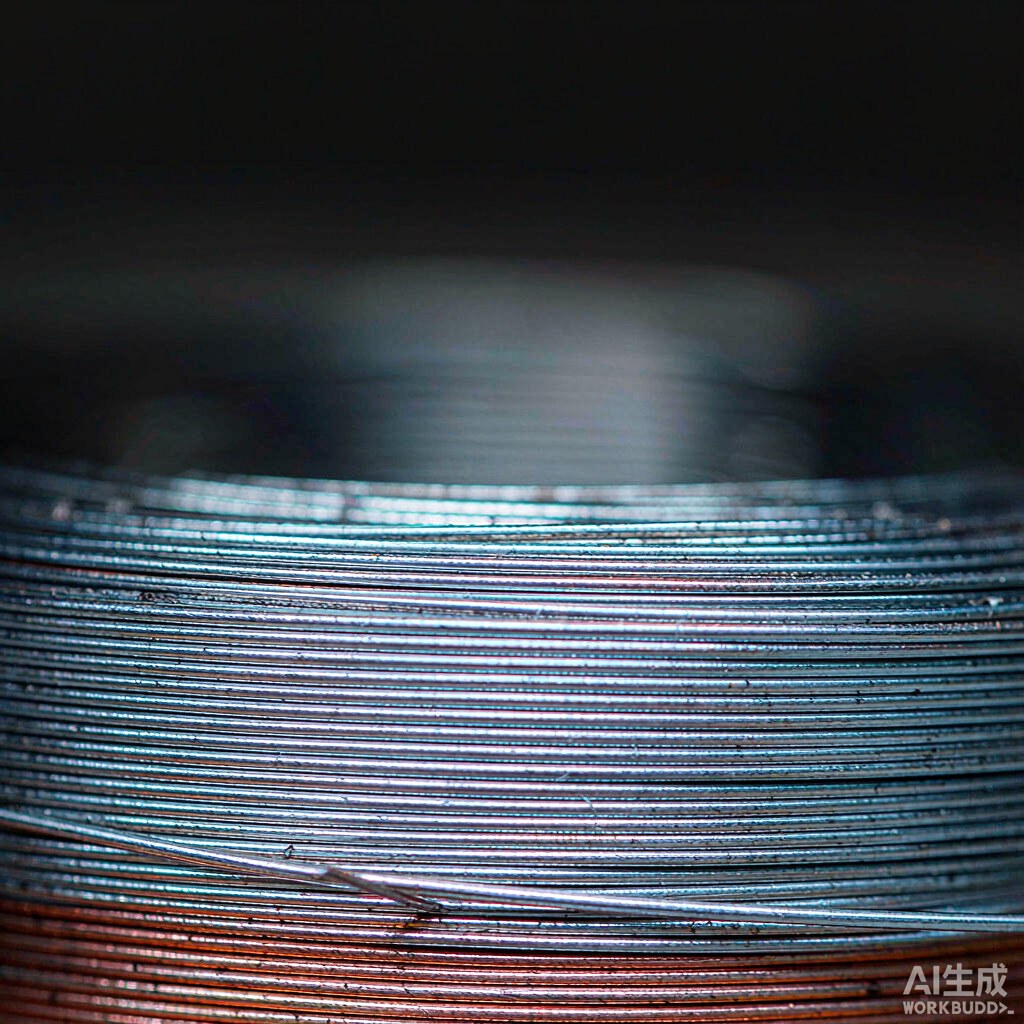
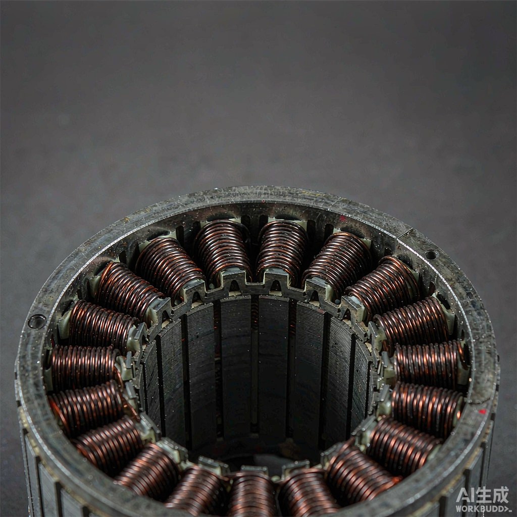
Fig. 1 - Close study of layered turns in a wound component. Illustrative image, AI-generated. Not a product photograph or a measurement record.
1. Where the Capacitance Comes From
Any two conductors at different potentials, separated by an insulator, store charge. In a coil, the neighbouring turns of one layer, the turns of adjacent layers and the leads running alongside the winding all create such pairs. The more conductor surface that faces another conductor across a thin insulating gap, the larger the effect. A winding with many parallel turns packed closely together therefore behaves differently from one where the same turns are separated, rearranged or shielded.
The important consequence is that turn count alone does not describe the part. Two windings with identical turns ratio and similar DC resistance can differ substantially in high-frequency behaviour because their turns were placed differently. That is why a drawing that specifies only turns, wire and bobbin may leave a significant part of the electrical result to the winding method.
2. Geometric Factors That Raise It
Facing area is the first factor: long runs of parallel turns with a large surface opposite each other increase the effect. Spacing is the second: thinner insulation or a shorter distance between conductors increases it. Layer count and layer ordering are the third, because they decide which turns end up adjacent and at what potential difference. Finally, how tightly the coil is packed changes the effective spacing and the amount of air or impregnation material between turns.
These factors interact. A change that reduces the number of layers may increase the number of parallel turns in each layer. Adding insulation between layers changes the spacing but also increases build-up, which can force a different winding window. Treating them as independent knobs leads to a design that looks better on one line of a calculation and worse as a physical coil.
3. What the Winding Process Can Actually Control
The winder controls layer ordering, traverse pattern, placement of interlayer material, tension and the resulting build. Layer ordering decides which conductors lie next to each other, and is one of the most powerful levers available to the process. Traverse determines how evenly turns are distributed across the winding width and whether local heaps create tight clusters. Interlayer insulation can be placed deliberately at defined points rather than left to chance.
Tension and build influence the effective spacing between turns and between layers. A loosely wound coil and a tightly packed one can differ in both geometry and in how much impregnation material remains between conductors. These are process settings, so they should be treated as controlled recipe items with a version, a first-article check and a change record, not as operator preferences.
| Choice | Effect on the winding | What must be recorded |
|---|---|---|
| Layer ordering | Decides which turns are adjacent | Winding sequence and start-finish positions |
| Traverse pattern | Distributes turns across the width | Pitch and reversal behaviour per layer |
| Interlayer material | Changes spacing between layers | Type, position and number of layers |
| Tension and build | Changes packing and effective spacing | Tension settings and finished dimensions |
| Lead routing | Adds capacitance near the exit | Lead path and separation from the winding |
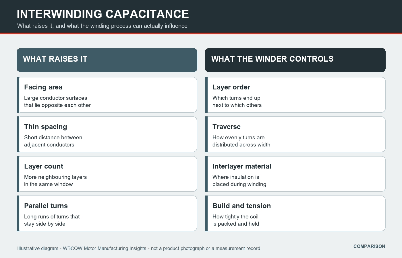
Fig. 2 - What raises capacitance on the left, what the winding process can control on the right. Illustrative diagram, not a product photograph or a verified test result.
4. Measurement and Interpretation Limits
Capacitance is not measured in isolation. The result depends on the test method, the fixture, how the winding terminals are connected, and whether other windings are shorted or left open during the measurement. A value obtained on a loose coil before assembly can differ from one measured in the finished component. Comparing two supplier results therefore requires that the conditions be stated, not just the number.
It is also easy to over-attribute a circuit problem to the winding. Core material, bobbin, shielding, layout and the measurement setup itself all contribute. A controlled comparison - two windings that differ only in layer ordering, measured the same way on the same fixture - is far more informative than a single absolute figure. Where possible, keep one part from each variant for later re-measurement.
5. Turning the Choice Into a Process Instruction
If the design team decides that a particular layer strategy is required, that decision has to reach the shop floor in a form an operator can follow. A drawing note saying that capacitance should be low is not a work instruction. The instruction should name the winding sequence, the start and finish positions, the interlayer material and its placement, the traverse settings and the lead routing, all under one program version.
The inspection plan should then check what the process can actually verify: the sequence by record, the layer count and placement by observation or section where appropriate, and the electrical result under stated conditions. Keeping the process record beside the measured result makes it possible to tell whether a deviation came from the winding or from the measurement.
6. Limits and a Practical Checklist
Winding choices can reduce or redistribute capacitance, but they cannot remove it, and they are constrained by insulation requirements, window space, thermal behaviour and manufacturability. A strategy that is elegant on paper but requires an impractical number of layer changes may not survive production. The useful goal is a repeatable process whose electrical consequence has been demonstrated on real parts, not a theoretical minimum.
Use this list when the winding method is being defined.
Ask which geometric factors the design actually cares about.
State the layer sequence and start-finish positions explicitly.
Define interlayer material, placement and the traverse settings.
Control tension and finished build as versioned recipe items.
Compare variants under identical, documented measurement conditions.
Keep representative parts from each variant for later re-measurement.
Interwinding capacitance is a reminder that a coil is a physical structure as well as a circuit element. Once that is accepted, the winding pattern stops being a manufacturing detail and becomes part of the design.