When a finished coil fails an electrical or assembly check, the winding process is often blamed first. In practice the weak point is frequently a few millimetres away: the stripped lead end, the weld or crimp, the bend where the lead leaves the coil, or the point where the lead is pulled during assembly. These steps may be performed by a different station, a different operator or even a different supplier, which is exactly why the fault is hard to trace.
This article offers a station-by-station way to separate the possibilities. It assumes no particular joint technology and quotes no acceptance limits, because those belong to the part specification. The aim is to make the first investigation quicker and the resulting evidence usable.

Fig. 1 - Abstract study of fine insulated conductor and connection points. Illustrative image, AI-generated. Not a product photograph or a measurement record.
1. Separate Winding Faults From Termination Faults
Start by comparing the failure with what the winding station can actually influence. An open circuit that appears only after the coil is handled suggests a lead or joint problem. A resistance shift that appears consistently on every part from one spindle suggests a winding or measurement problem. A fault that follows a program change points one way; a fault that follows a change of lead wire batch or weld schedule points another. Recording when the symptom first appeared is often more diagnostic than any single measurement.
A simple comparison helps: measure a sample at the winding station, then again after termination, then again after any assembly handling. If the value is stable at the first two points and changes at the third, the search should start with routing and strain relief. If it changes immediately after the joint, look at preparation and joint quality instead.
2. Enamel Removal and Lead Preparation
Fine enameled wire has to be stripped without nicking the conductor. Incomplete removal leaves an insulating film that produces a high-resistance or intermittent joint; over-aggressive removal reduces the conductor section and creates a mechanical weak point. Both failures can look similar at final test, and neither is visible once the joint is covered. Check the stripped length, the appearance of the conductor under magnification and the consistency across a batch of leads.
Lead wire condition matters too. Stored wire with oxidised or damaged ends, a changed insulation grade or a different strand count will alter how the joint forms even when the welding schedule is unchanged. Keep the lead wire identity in the same record as the joint settings, so that a batch change can be tested as a hypothesis rather than guessed at.
3. Weld, Crimp and the Surrounding Area
A joint can be electrically sound and mechanically fragile. Heat affected zones, spatter, inconsistent pressure and poor positioning can damage enamel on adjacent turns or leave a sharp edge that later cuts through insulation. Crimped joints bring their own variables: terminal size, crimp height, tool wear and whether the fine wire is supported inside the crimp. In both cases, a joint that passes a pull check once can still fail after vibration or thermal cycling.
Inspect the region around the joint, not only the joint itself. Look for discoloured enamel, displaced turns, stray strands and contact with the coil body. If the process uses heat, compare parts made at the start and end of a run, since tool temperature can drift. Any pattern tied to time, tool or operator is useful evidence for the next step.
| Symptom | Likely stage | First check |
|---|---|---|
| Open circuit after handling | Lead routing or strain relief | Bend radius and where the load is carried |
| High or unstable resistance | Enamel removal or joint | Stripped length and conductor appearance |
| Intermittent fault under movement | Joint or lead exit | Pull gently while monitoring continuity |
| Enamel damage near the exit | Heat or sharp edges | Discolouration, spatter and stray strands |
| Failures grouped by shift | Setup or operator method | Joint settings and tool condition by time |
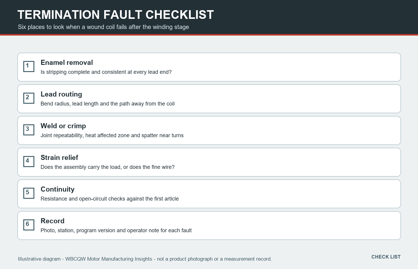
Fig. 2 - Six places to inspect when a wound coil fails after the winding stage. Illustrative diagram, not a product photograph or a verified test result.
4. Lead Routing, Bend Radius and Strain Relief
Fine wire does not tolerate being used as a mechanical support. A lead that exits the coil at a sharp angle, crosses a flange edge or is pulled tight during assembly will concentrate stress at the point where the conductor leaves the enamel. Strain relief should transfer the load to the bobbin, the housing or a dedicated fixing, not to the winding itself. The routing path, the permitted bend radius and the fixing point belong on the drawing and in the work instruction.
Assembly is often where the damage happens, so include that station in the investigation. A coil that passes every in-house check can fail after a connector is pushed into place or a cover is closed. A short observation of the assembly motion, with a continuity check at the same time, frequently reveals a fault that static inspection cannot.
5. Build a Fault Map That Points Back to a Station
A useful fault record captures four things: the symptom, the last station at which the part was known good, the configuration at that moment, and a photograph of the failed area. Configuration includes the winder program version, the lead wire batch, the tool or electrode identifier, the operator and the time. With those fields, a cluster of failures can be tested against a specific change. Without them, every investigation starts again from memory.
Keep failed parts rather than discarding them after a visual check. A small box of samples grouped by failure type is more informative than a spreadsheet of pass counts, because it lets an engineer compare the physical evidence when a new hypothesis appears. It also makes discussions with a supplier concrete: the conversation is about a part and a station, not about general quality.
6. Limits and a Practical Checklist
Not every termination failure has a single root cause. Several small weaknesses can combine, and a checklist cannot replace a controlled experiment where the process allows one. It can, however, stop the two most expensive habits: re-adjusting the winder when the fault is downstream, and re-working joints when the fault is actually in the winding. Both waste time and can introduce new variation.
Work through this sequence before changing any setting.
Measure at winding, after termination and after assembly handling.
Inspect stripped length, conductor condition and adjacent enamel.
Check joint repeatability, tool condition and heat affected area.
Verify lead routing, bend radius and where assembly loads are carried.
Record program version, wire batch, tool, operator and time for each fault.
Retain grouped failed samples for physical comparison.
A termination is a small part of the coil, but it is where the electrical result meets the mechanical world. Treating it as a distinct process with its own records makes most failures traceable on the first pass.