Most stator winding discussions assume a cylindrical bore with slots running along the axis. An axial-flux machine arranges the active conductors on a flat or disc-shaped structure, with the air gap facing along the axis. That single geometric change propagates through the whole winding route: how the part is held, how turns are placed, where the end turns go, how the finished piece is bonded and how it is tested. Equipment designed around a radial stator cannot simply be pointed at a disc.
This article describes the process questions an axial-flux stator raises. It is deliberately design-neutral: no particular topology, slot count or performance number is assumed, and supplier-stated capabilities are treated as claims that need to be demonstrated on the actual part.
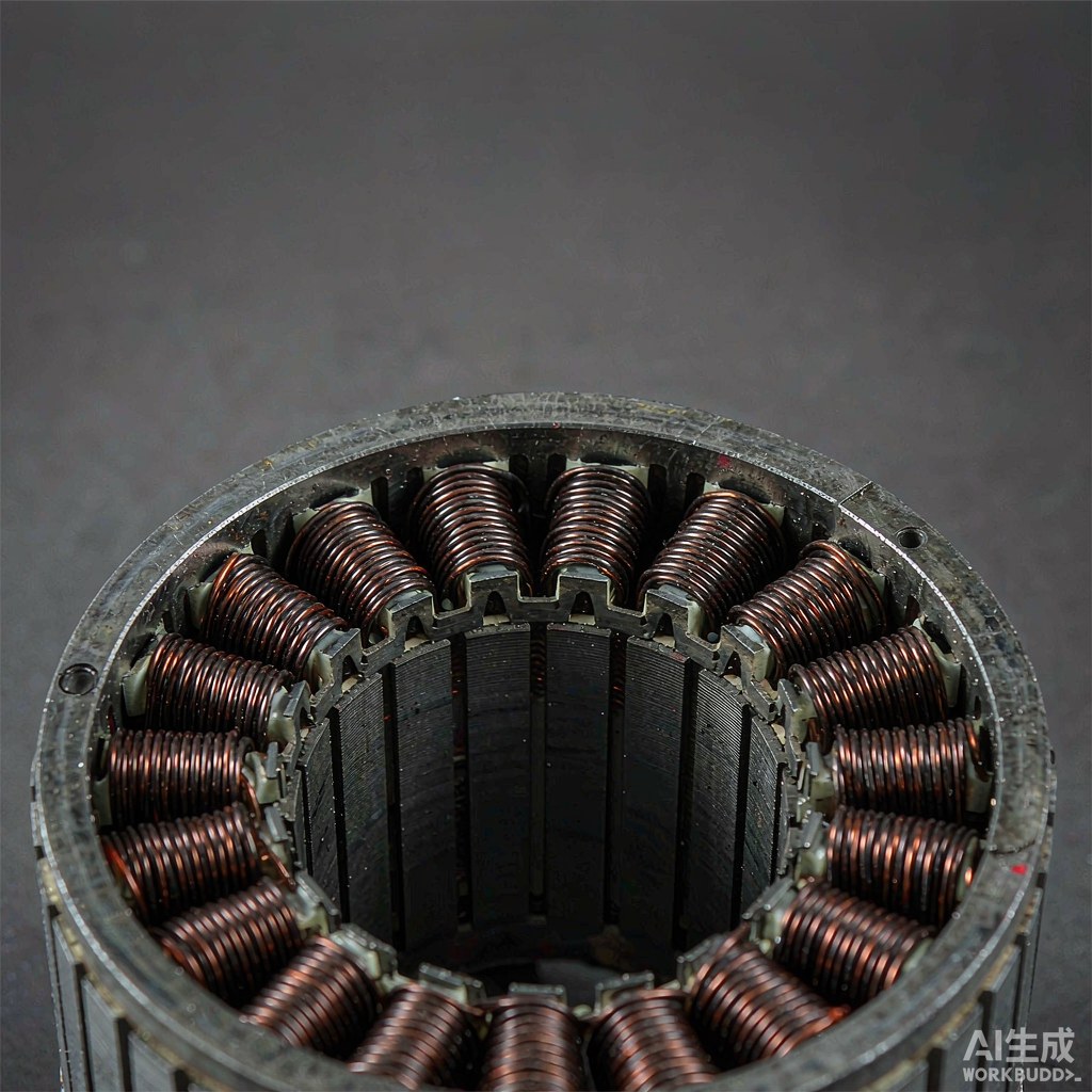
Fig. 1 - Overhead study of a wound stator showing repeated copper coil positions. Illustrative image, AI-generated. Not a product photograph or a measurement record.
1. Translate the Geometry Into a Holding Problem
The first question is not how to wind but how to hold the part. A disc-shaped or segmented stator presents a flat face, an inner diameter and an outer diameter, and it may arrive as separate pieces rather than one continuous core. The fixture must locate each piece accurately, resist winding forces without flexing, and allow the wire to reach the winding area without crossing a sharp edge. Indexing between segments, where used, becomes part of the winding cycle rather than a separate assembly step.
Handling before and after winding matters just as much. A flat part can be supported differently from a cylindrical one, and a segmented part may need to stay in a carrier until all pieces are joined. Ask to see the loading and unloading sequence, not only the winding motion, because that is where a surprising amount of the cycle time and the variation usually sits.
2. Traverse and End-Turn Routing Change Character
In a cylindrical stator, traverse is commonly thought of as motion along the slot. On a disc, turns are placed across a face with a radial dimension, so the relationship between traverse, pitch and the inner and outer diameter becomes a central program question. The same turn count can be distributed in several ways, and the chosen pattern affects how much conductor sits near the inner radius, where space is usually tighter.
End turns also need a defined route at both diameters. They must be kept clear of adjacent segments, the air-gap face and any later assembly interface, while staying within the insulation margins. A program that produces a neat winding on the face can still create a problem at the edges, so the acceptance view should include the inner and outer perimeter, not just the visible top surface.
3. Bonding, Segments and Symmetry
Where the design uses separate coils or segments, the turns must be fixed before the piece is moved. Bonding, tape or a later impregnation step therefore belongs in the same controlled recipe as the winding itself, with its conditions recorded. A coil that shifts before it is fixed will change the geometry of the assembled disc, and a shift that is small on one segment can become a noticeable imbalance when repeated around the whole structure.
Symmetry is a process concern, not only an electromagnetic one. If every segment is wound on the same fixture with the same program, a systematic error repeats consistently; if segments are handled or indexed differently, the variation between them becomes the thing to control. Recording which fixture, program version and carrier produced each segment makes that comparison possible.
| Factor | Why it matters on a disc stator | Process question |
|---|---|---|
| Flat coil geometry | Differs from a cylindrical slot shape | Which fixture locates the part |
| Traverse | Turns distributed across a radial face | How pitch is defined at inner and outer diameter |
| End turns | Routing at both diameters | What keeps them clear of the air-gap face |
| Segments | Parts may be wound separately | How indexing and identity are maintained |
| Bonding | Turns must be fixed before movement | Which step fixes them and how it is verified |
| Test access | Probes must reach the finished part | Where measurements are taken after assembly |
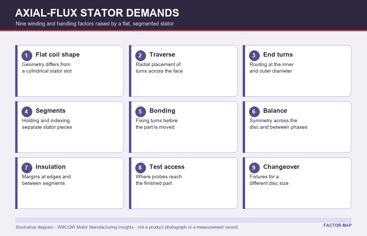
Fig. 2 - Winding and handling factors raised by a flat, segmented stator. Illustrative diagram, not a product photograph or a verified test result.
4. Insulation Margins and Test Access
A flat stator brings conductors close to edges, to neighbouring segments and to the assembly interface. Creepage and clearance margins therefore need to be defined on the drawing and checked on the finished piece, including at the inner and outer diameters where the end turns are routed. Insulation that is adequate on the face can be marginal at a corner, and a corner is exactly where handling damage tends to occur.
Test access is the other practical constraint. The measurements that matter may be easier before the segments are joined and harder afterwards, or the reverse. Decide at which stage each check is performed, and record the stage alongside the result. If a value is only measurable on the assembled disc, the process needs a clear route for reworking or quarantining a part that fails late.
5. Changeover and What to Ask a Supplier to Demonstrate
A different disc diameter, segment count or coil shape can require different fixtures, a different traverse strategy and a revised program. Changeover is therefore part of the equipment specification, not an afterthought. Ask which items change, how long the change takes in a demonstrated sequence, and what must be re-verified with a first article afterwards. A machine that handles one disc well but needs a full re-engineering for the next size is a different purchase from a flexible platform.
For evidence, ask for a run on your own part or a representative sample, with the winding face and both diameters documented, plus the loading and unloading sequence. Ask which figures in the quotation are supplier-stated and which were observed in that run. Keep that distinction in the acceptance record.
6. Limits and an Evaluation Checklist
Equipment capability is only one part of whether an axial-flux design can be produced consistently. The winding route cannot fix an insulation margin that is too small, a segment joint that cannot be accessed for test, or a disc that distorts during bonding. Those are design decisions with manufacturing consequences, and they should be reviewed together with the people who will run the process.
Use this list when comparing equipment.
See the loading, indexing and unloading sequence on a real part.
Map traverse and pitch at both the inner and outer diameter.
Define the end-turn route and the clearance reserved for it.
Record which fixture, carrier and program version made each segment.
Confirm insulation margins at edges and corners on the finished piece.
Document changeover parts, program changes and first-article re-verification.
An axial-flux stator does not demand exotic winding in principle. It demands that every assumption borrowed from cylindrical stator practice - holding, traverse, end turns, bonding and test - be made explicit again for a flat geometry.