A bobbin is more than a convenient thing to wind onto. It locates the first turn, holds the flanges apart, provides part of the insulation system and keeps the finished coil rigid when it leaves the spindle. A bobbinless coil has to get all of those functions from somewhere else: a temporary mandrel, the bonding of the wire itself, tape or an impregnation step, and careful handling until the part is stable. That is why two coils with similar turn counts can demand quite different winding equipment and quite different process evidence.
This article compares the two routes across tooling, insulation, handling and machine control. It does not assume a particular bond system or a particular part geometry, and it treats supplier statements about capability as claims to be demonstrated rather than as specifications.
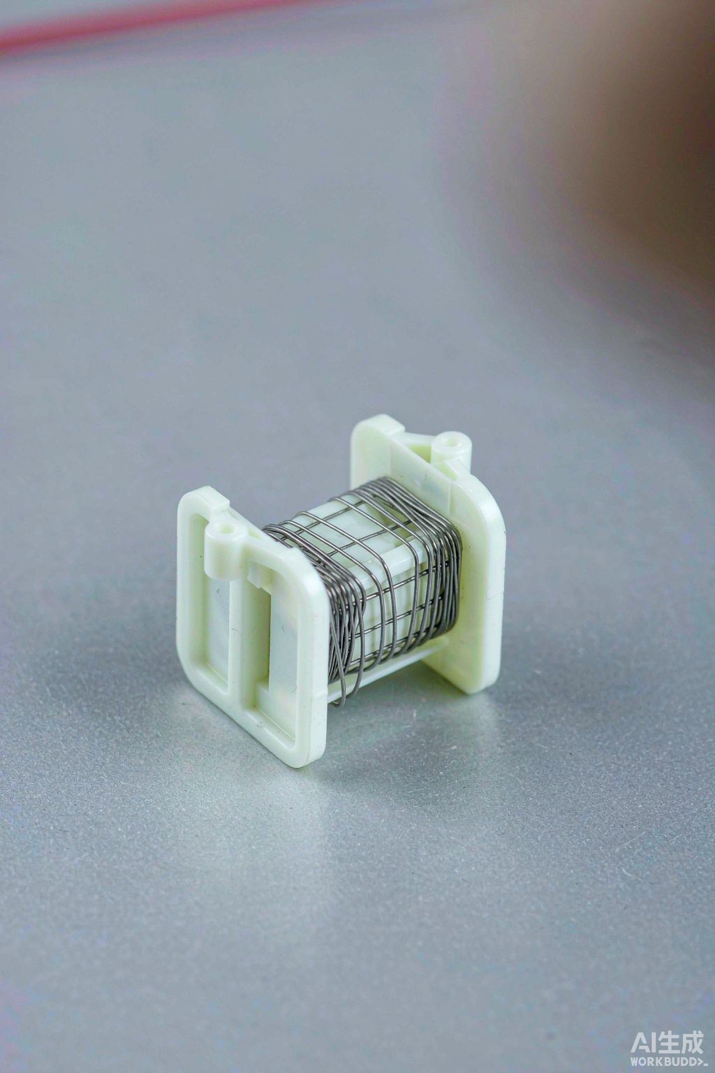
Fig. 1 - A coil former component shown as an isolated part study. Illustrative image, AI-generated. Not a product photograph or a measurement record.
1. What Actually Changes When the Bobbin Is Removed
With a bobbin, the winding window is defined by physical flanges and the coil is supported continuously during winding. Without one, the window is defined by temporary tooling that must later be taken away, and the coil must hold its own shape during that removal and afterwards. The design may gain useful space or reduce a component, but it transfers several jobs from a moulded part to the process. Every one of those transferred jobs needs a control, otherwise the benefit is paid for in variation.
It is worth separating the two decisions. The electrical design decides whether a bobbin is needed for insulation, creepage and assembly. The manufacturing process decides whether the winding route can make that design repeatably. A coil that is electrically attractive but cannot survive removal from a mandrel is a process problem, not a reason to relax the drawing.
2. Tooling: Mandrels, Flanges and Release
A bobbinless coil is usually wound on a mandrel with temporary flanges or a shaped fixture. That tooling must locate the wire accurately, resist the winding forces without deflecting, and release cleanly without dragging turns out of place. Surface finish, release treatment and the direction of removal all matter. If the bond has already set before removal, the tooling must also tolerate the bonding step; if it has not, the part must be transferred without disturbing the turns.
Changeover looks different too. A bobbin-based machine may only need a different bobbin and a program, while a bobbinless route may need a different mandrel, different flanges and a revised removal sequence. Ask which of these are part of the standard scope and which are options, and ask to see the sequence on a real part rather than only in a drawing.
3. Insulation and Bonding Take Over From the Bobbin
Self-bonding wire, applied tape, heat, solvent or a later impregnation step can hold the turns together. Each route introduces a process window: activation temperature or time, pressure during bonding, cure before handling, and compatibility with the enamel and with any interlayer material. These are process conditions to be recorded and repeated, not details that can be left to operator judgement. A coil that looks correct immediately after winding can still relax or distort if the bonding step was incomplete.
Insulation planning also changes. Where a bobbin once provided a barrier, the designer now needs a defined margin between conductors and between the coil and its surroundings. That margin has to survive winding, bonding, handling and assembly. It should be specified on the drawing and checked on a finished part, not inferred from the wire datasheet.
| Aspect | With a bobbin | Bobbinless |
|---|---|---|
| Support during winding | Flanges and core hold every turn | Temporary mandrel and fixture |
| Insulation path | Bobbin is part of the system | Wire enamel, tape, bond and margins |
| Shape after winding | Part stays rigid at the spindle | Depends on bond cure and removal |
| Tooling changeover | Bobbin plus program | Mandrel, flanges, sequence and program |
| Main failure risk | Flange damage and window limits | Collapse, distortion and poor release |
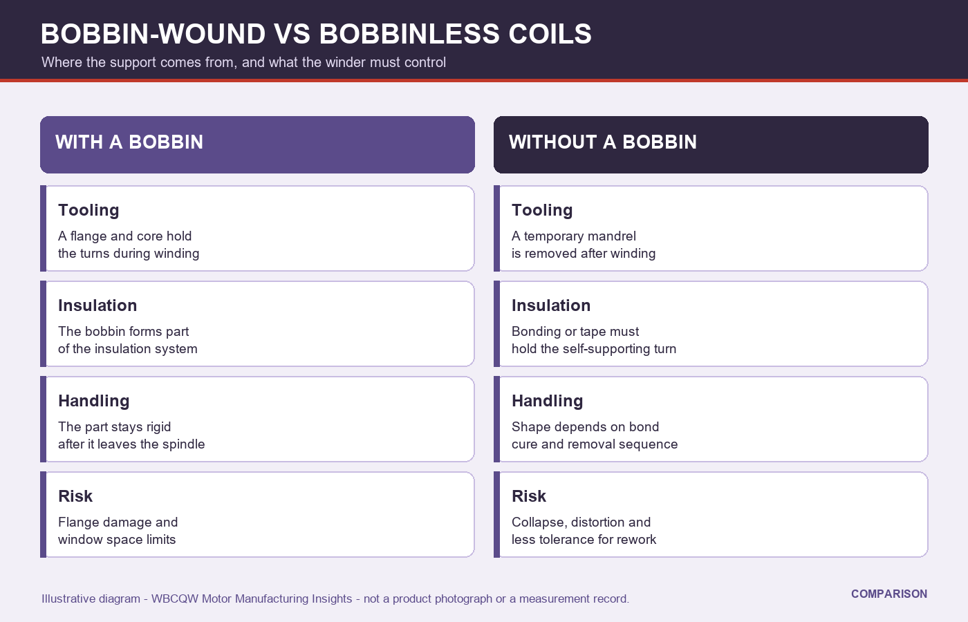
Fig. 2 - Tooling, insulation, handling and risk compared across the two coil routes. Illustrative diagram, not a product photograph or a verified test result.
4. Handling and Dimensional Stability
Once the coil leaves the winding station, a bobbinless part enters its most vulnerable period. Lifting, stacking, transfer to a bonding station and placement into an assembly can all change its shape. Fixtures, trays and handling instructions become part of the process definition. Dimensional checks should be made after the part has stabilised, not only while it is still on the mandrel, because that is the condition the next station actually receives.
This has a direct effect on what an acceptance record must contain. Measuring the coil before release from the tooling answers a different question from measuring it after bonding and cooling. If only the first measurement is recorded, a systematic shift after handling can remain invisible until assembly. A short before-and-after comparison on the first articles is usually enough to show whether the shift matters.
5. What the Winder Has to Control
The machine side of the decision is mostly about consistency. Tension must be held within a window that packs the turns without stretching them, because a bobbinless coil has no flange to correct a loose layer. Traverse must place turns evenly, since local heaps create weak points and change the outer profile. If bonding is applied during winding, the heat or activation step must be repeatable and must not damage adjacent turns or the temporary tooling.
The program should therefore be treated as a controlled recipe that includes the removal and bonding sequence, not just the spindle and traverse settings. Version control, a first-article check and a change record matter more here than on a forgiving bobbin-wound part. Where a supplier states a capability, ask which of these controls produced the demonstrated result.
6. Limits and a Selection Checklist
Neither route is universally better. A bobbin adds a component and consumes space, but it simplifies handling and makes insulation easier to define. A bobbinless coil can save space and mass, but it moves complexity into tooling, bonding and process control. A fair comparison counts all of those costs, including the extra fixtures, the bonding step and the inspection needed after release, rather than comparing only the piece part.
Use this list before choosing a route.
State which insulation and creepage functions the bobbin used to provide.
Define the mandrel, release direction and release condition on the drawing.
Record the bonding window and how completeness is verified.
Measure the finished part after bonding and handling, not only on the tool.
Include fixtures and trays in the process definition.
Keep the winding, bonding and removal steps under one controlled program version.
The useful question is not whether a coil can be wound without a bobbin. It is whether every job the bobbin used to do has been given a new, controlled and verifiable owner.