A winding program is written in numbers, but a coil is built in two directions at once. Traverse motion places turns side by side along the bobbin axis, while each completed layer grows the coil outward from that axis. Drawings, programs and inspection reports often use words such as pitch, width, clearance and fill factor without saying which direction they mean. The result is a familiar pattern: the program is correct by its own definitions, the drawing is correct by its own dimensions, and the finished part still surprises somebody.
This article is a vocabulary guide rather than a design method. It defines the common terms in plain language, shows how they interact, and lists the questions to ask when a specification is ambiguous. No dimensions or tolerances are assumed, because those belong to the part drawing and should never be inferred from a glossary.

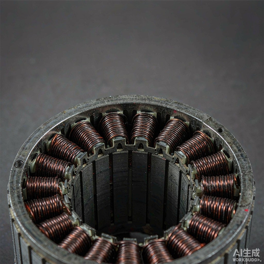
Fig. 1 - Close view of a wound coil end face showing layered turns. Illustrative image, AI-generated. Not a product photograph or a measurement record.
1. Two Directions, Four Common Confusions
The axial direction runs along the bobbin axis, from one flange towards the other. The radial direction runs away from that axis, from the core towards the outside of the finished coil. Traverse, winding width and pitch belong mainly to the axial direction. Build-up, flange clearance and most uses of fill factor belong mainly to the radial direction. Confusing them is easy because a single program parameter can influence both: a change in pitch changes how many turns fit in a layer, which changes how many layers are needed, which changes the radial build.
A second confusion comes from units. A drawing may dimension the available window while a program expresses traverse in machine units, pulses or a percentage of travel. Before discussing whether a value is correct, establish what the value is measured from and in what unit. Many disputes that look like technical disagreements are really two people describing different reference points.
2. Axial Terms: Traverse, Winding Width and Pitch
Traverse is the side-to-side motion that distributes turns across the winding width as the spindle rotates. Winding width is the axial space available for those turns, normally bounded by flanges or by a defined margin. Pitch is the axial advance per turn, which is related to wire diameter but is not the same thing: insulation thickness, traverse dynamics and the intended spacing between turns all influence the value that actually gets used. Layer reversal is the point where the traverse changes direction at the end of a pass.
These terms describe placement, not quantity. A given winding width can hold a different number of turns depending on pitch, and the same pitch can produce a different appearance depending on how the reversal is managed. That is why a specification that states only turn count and wire diameter leaves an important part of the geometry undefined.
3. Radial Terms: Build-Up, Fill Factor and Clearance
Build-up is the radial growth of the coil as layers accumulate. As it grows, the distance from the tensioner to the contact point changes and the effective winding diameter changes, so tension and traverse behaviour late in the winding can differ from the first layer. Flange clearance is the remaining radial space between the finished outer surface and the flange rim or the next mechanical limit. It is the margin that absorbs insulation, tape and dimensional variation.
Fill factor describes how much of an available window is occupied by conductor rather than by insulation, air and voids. It is a ratio, so it is only meaningful when the window is defined: the whole slot, the bobbin window or the coil cross-section can all be used as the denominator. Two teams can quote different fill factors for the same coil without either being wrong, simply because they chose different boundaries.
| Term | Direction | Plain meaning | Usual mix-up |
|---|---|---|---|
| Traverse | Axial | Motion that distributes turns across the width | Confused with spindle rotation |
| Winding width | Axial | Space available between flanges or margins | Confused with overall bobbin length |
| Pitch | Axial | Advance per turn along the axis | Assumed equal to bare wire diameter |
| Build-up | Radial | Growth of the coil as layers are added | Assumed linear for every layer |
| Fill factor | Radial / area | Share of a defined window filled by conductor | Denominator left undefined |
| Flange clearance | Radial | Space left at the finished outer surface | Omitted from insulation planning |
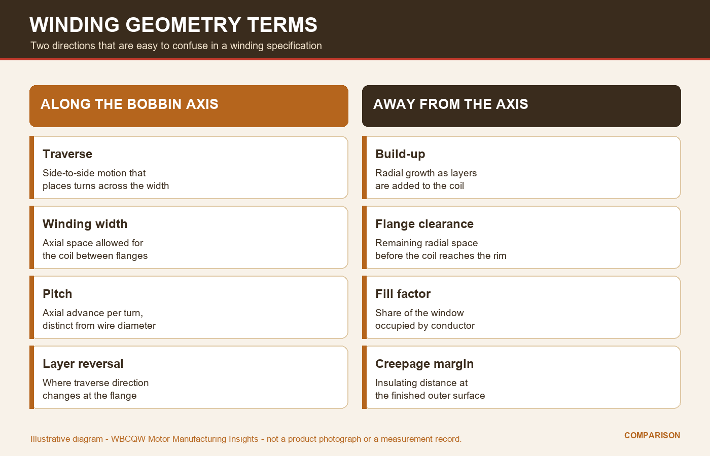
Fig. 2 - Axial and radial geometry terms shown side by side with plain definitions. Illustrative diagram, not a product photograph or a verified test result.
4. How the Terms Interact Inside a Program
Consider a simple change: pitch is reduced so that turns sit closer together. More turns now fit into one axial pass, so a given turn count may need fewer layers, and the radial build at the end is smaller. But the reversal points are still at the flanges, and the wire now spends more time near them, so the reversal behaviour and the local build at the edges become more important. A parameter that looked purely axial has changed the radial result.
The reverse also happens. Adding interlayer insulation increases build-up and consumes flange clearance, which changes the effective winding diameter, which in turn affects the length of wire per turn and the tension demand. Once the coil is near its radial limit, a small change in placement can force a different layer strategy. Program settings should therefore be reviewed as a set, with a sketch of the intended cross-section, rather than optimised one line at a time.
5. Where Documents Get Ambiguous
The word pitch is the most frequent source of trouble because it is used in both winding and general mechanical contexts. Layers are counted differently when a reversal pass is or is not treated as a full layer. Clearance may be specified from the flange rim, from the insulation surface or from a nominal envelope. Build-up may be described as a finished dimension or as an allowance. None of these conventions is wrong, but a document that does not name its convention is incomplete.
The cheapest fix is a single annotated cross-section attached to the specification, showing the axial reference point, the width being dimensioned, the radial reference and the clearance being reserved. Ask the supplier to map each program parameter to a feature on that sketch. If a term cannot be pointed at on the drawing, it should be defined in words before it is used in an acceptance criterion.
6. A Short Working Glossary Checklist
A shared vocabulary does not remove the need for measurement, but it does remove a large class of avoidable disagreement. It is worth agreeing the definitions at the start of a project, recording them in the part dossier, and reusing the same wording in the program sheet, the inspection plan and any change request. That consistency matters more than the particular convention chosen.
Use this list when a specification arrives.
State which direction each term refers to: along the axis or away from it.
Name the reference point and the unit for every axial dimension.
Define the window used as the denominator of fill factor.
Show where flange clearance is reserved for insulation and tape.
Attach an annotated cross-section to the program sheet.
Reuse the same definitions in inspection records and change requests.
Geometry terms are not academic. They are the interface between a drawing, a program and a physical coil, and a few minutes spent fixing their meaning prevents hours of arguing about a part that was built exactly as somebody described it.