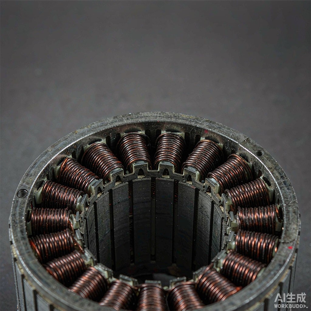
When winding consistency degrades, the first suspect is usually the program or the wire lot. In practice the cause is often a small part that costs very little: a guide with a polished groove worn into it, a tensioner felt that has glazed over, or a nozzle whose exit radius has been rounded by months of fine wire. These components define the force and the path the conductor actually experiences, and they change slowly enough that nobody notices the drift until scrap rises. This guide looks at the wear parts themselves, how to inspect them, and what a useful spare parts list contains. It is deliberately about hardware, not the root-cause diagnosis of fine wire breakage, which starts from the symptom rather than the component.
Why consumables dominate consistency
A winding machine controls the spindle, the traverse and, on better-equipped models, the tensioner. Everything between the spool and the coil is passive hardware, and passive hardware wears. The controller may hold exactly the same setpoint for a year while the friction at a guide increases by a third, so the wire sees a different force from the one the program believes it is applying. The result is a gradual shift in packing, resistance and breakage rate that looks like a process mystery.
Two properties make these parts worth managing. First, wear is local: one grooved guide affects one machine, which is why a fleet behaves inconsistently even with identical programs. Second, wear is invisible in most data logs, because a machine without a tension sensor has no way to report it. That is why a scheduled physical inspection, with a simple record, adds more control than another software feature. Treat guides, tensioner elements and nozzles as measuring instruments that happen to be mechanical.
Wire guides: material, groove and wear marks
Guides are selected for hardness, surface finish and compatibility with the enamel. Ceramic, hardened steel and coated options each behave differently with fine wire, and a material that suits a thick conductor can abrade a thin one. The useful inspection is not a visual check for damage but a check of the contact surface under magnification: a polished flat, a shallow groove, a chip at the entry radius or embedded copper dust all change the friction and can cut the enamel.
Record the contact angle and the number of guides in the path as part of the setup sheet. If a guide is replaced, re-check the tension trace or the gauge reading, because a new surface with lower friction changes the force reaching the coil even when the setpoint is untouched. Rotate or replace guides as a set where the design allows it, and keep the removed part labelled with its hours in service. Over a few months that record tells you the real replacement interval for your wire, which is almost never the interval in a generic manual.
Tensioners: open loop versus closed loop hardware
An open-loop tensioner applies a set resistance through a brake, felt pad or magnetic element and assumes the path stays constant. Its accuracy depends entirely on calibration and on the condition of the friction surfaces, so a glazed pad or a contaminated disc produces an offset that no parameter change can correct. A closed-loop unit measures the wire and adjusts an actuator; it removes some of that drift, but introduces a sensor, a feedback loop and a moving part that themselves need checking.
Whichever type is fitted, inspect the mechanical side on a schedule. Check felt and pad condition, disc cleanliness, pulley bearing freedom, and whether the dancer or sensor arm returns freely to the same position. Verify the reading against an independent gauge at a fixed point in the path, at the same speed used in production. A closed-loop display that disagrees with a handheld gauge is a maintenance signal, not a reason to change the setpoint. Keep the verification trace with the machine file so a later argument about drift starts from evidence.
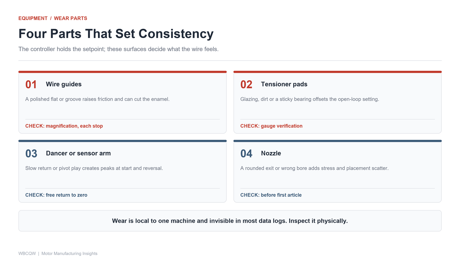
Fig. 1 - Four wear parts, the symptom each one produces and the effect on the coil. Illustrative diagram, not a product photograph.
Nozzles and bending radius
The nozzle is the last thing the wire touches before it becomes a coil, so its exit geometry sets the bend the conductor must accept. A rounded or chipped exit, a burr from cleaning, or an incorrectly sized bore relative to the wire diameter all raise local stress. With fine enameled wire, a nozzle that is too tight also traps heat and debris; one that is too loose lets the wire wander, which shows up as inconsistent traverse placement rather than as an obvious defect.
Inspect the exit under magnification and pass a short length of wire through by hand to feel for drag. Replace rather than polish a worn nozzle unless the maker explicitly allows rework, because polishing changes the radius that the program was tuned around. Also check the nozzle mounting angle and its distance to the part: a nozzle moved during a fixture change alters the free length of wire, which changes both the tension peak at reversal and the placement of the first turn.
A wear-part inspection schedule
Build the schedule from your own evidence. Start with a short interval, record the condition of every contact part at each check, and extend it only after several cycles show no measurable change. Tie inspections to a trigger as well as to the calendar: after every wire lot change, after a fixture change, after any breakage event, and before a first-article run. A check that takes five minutes is cheaper than a day of chasing a resistance shift that turns out to be a grooved guide.
Make the record simple and physical: date, machine, hours or parts since last change, part number replaced, wire lot, and a short note on surface condition. Photograph anything unusual. This is also where the limits of the approach should be stated. Replacing wear parts restores the machine to its intended condition; it cannot compensate for a wire path with too many wrap angles, a bending radius that was wrong from the design stage, or a program whose peaks exceed what the conductor can tolerate.
| Part | Wear symptom | Inspection interval | Effect on the coil |
|---|---|---|---|
| Wire guides | Polished flat, groove, chip, copper dust | Each scheduled check and after a break | Higher friction, enamel damage, uneven packing |
| Tensioner pads or discs | Glazing, contamination, sticky bearing | Scheduled check plus gauge verification | Offset from setpoint, drifting resistance |
| Dancer or sensor arm | Slow return, play in pivot, zero offset | Each scheduled check | Tension peaks at start and reversal |
| Nozzle | Rounded exit, burr, wrong bore, debris | Before every first-article run | Placement scatter, wire stress, breaks |
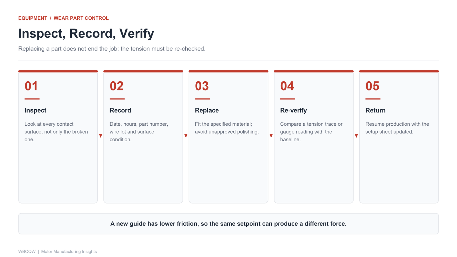
Fig. 2 - Inspect, record, replace, then re-verify tension before returning to production. Illustrative diagram, not a product photograph.
What to ask for in the spare parts list
A useful spare parts list gives part numbers, materials, the exact position in the wire path, compatible wire diameter range, and a recommended inspection interval with the reasoning behind it. It should distinguish consumables from long-life components and state which items must be replaced as a set. Ask whether the guide and nozzle materials are the same as those used in the factory acceptance test, and whether a change of supplier or specification would be communicated. A list of generic names with no part numbers makes a repeat order a guessing game.
Xingte Technology, based in Shenzhen, supplies multi-axis precision winding machines, stator and rotor winding machines, and standard and customized automation solutions for automotive electronics, robotics, UAV and optical module production, with sample testing, on-site commissioning and after-sales support. For any supplier, ask for the wear-part documentation during technical evaluation and keep it with the setup baseline. A machine is only as consistent as the surfaces its wire touches, and those surfaces are the first thing that changes with use.