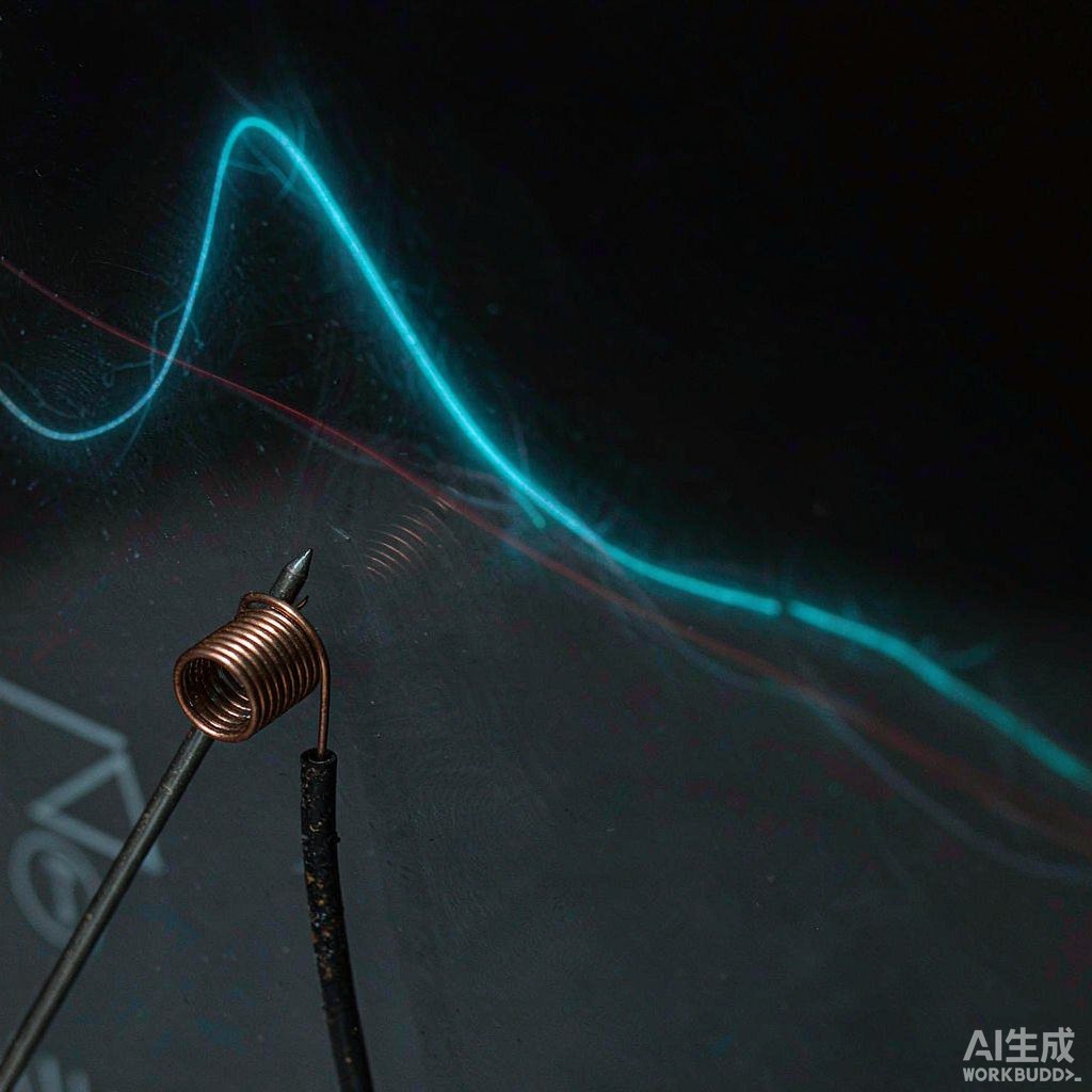
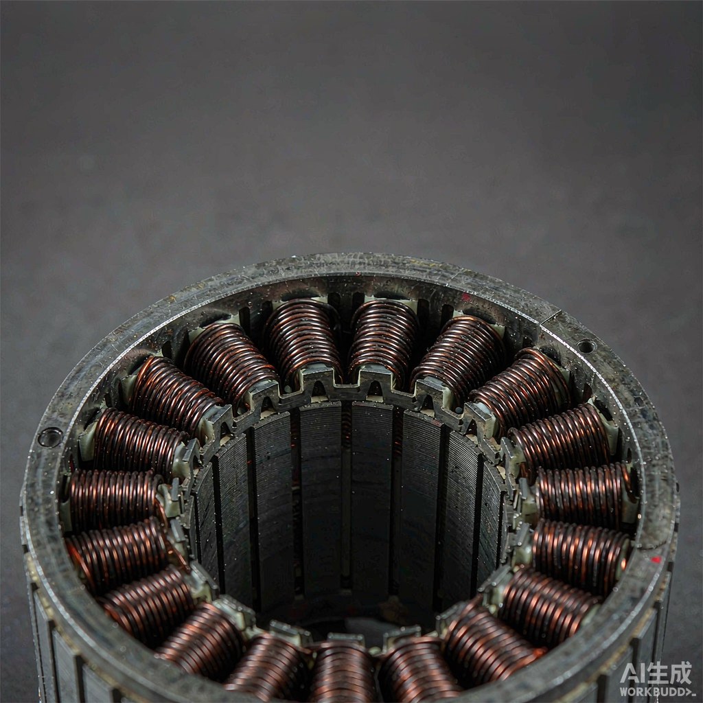
Inductors, transformers and sensor coils are wound parts, and at a glance they look like a smaller, simpler version of a motor stator. The equipment buyer who acts on that impression usually discovers the difference at the sample stage. Magnetic components are governed by turns ratio, coupling and leakage behaviour, by core geometry and by the insulation margin of very fine wire, rather than by slot fill and end-turn envelopes. This guide sets out those constraints, states where stator winding equipment does not fit, and gives a question list for briefing a supplier. For motor-side process background, see our overview of winding machine types and processes.
A different family of wound parts
A stator winding converts current into a rotating field inside a slot. An inductor stores energy in a magnetic circuit whose core may be assembled after winding; a transformer transfers energy between two or more windings whose relative position is the design. In both cases the number of turns and their arrangement set the electrical behaviour directly. A single misplaced turn can change leakage or coupling even when resistance and dimensions look correct.
That shifts what has to be controlled. Repeatability of turn placement, winding direction, start and finish identification, and the physical relationship between multiple windings matter more than gross packing density. The part is also often smaller, with a bobbin or former that stays in the finished assembly. Fixturing, lead dressing and the release method become part of the process specification rather than an afterthought.
Bobbin and core geometry
Start with the former. State its material, flange dimensions, winding window, any split or sectioned structure, and the direction in which the core will be inserted. A bobbin designed for manual winding may not tolerate the clamping force or the traverse path of an automated head. Where a magnetic core is fitted after winding, the winding must leave enough clearance and must not be distorted by core insertion. Ask for a sample assembly, not just a wound bobbin.
Core geometry also affects the test. Inductance depends on the core, its air gap and its position, so a measurement taken before assembly is not comparable with one taken afterwards. Agree the test state explicitly: bare coil, coil with core, or finished assembly, and with what fixture. A supplier and a customer can easily measure the same part and disagree simply because one measured it on a bench and the other in its housing.
Turns ratio and leakage targets
For a transformer or a coupled inductor, the ratio between windings and the leakage between them are functional requirements. They are influenced by the number of turns, the order of winding, the separation or interleaving of sections, and the repeatability of the traverse. A program that produces the correct turn count on both windings can still fail if the layering order or the section width drifts. These are geometry controls, and they should be written into the setup sheet with a measurement method.
Ask how the supplier verifies turns ratio and leakage, at what frequency and with what instrument, and whether the measurement is taken on every part or on a sample. Where multiple windings share a former, ask how the start and finish of each are identified and recorded; a correct winding with two leads swapped is a faulty part. Also ask for the retained reference part. When a batch drifts later, that reference is what separates a process change from a test fixture change.
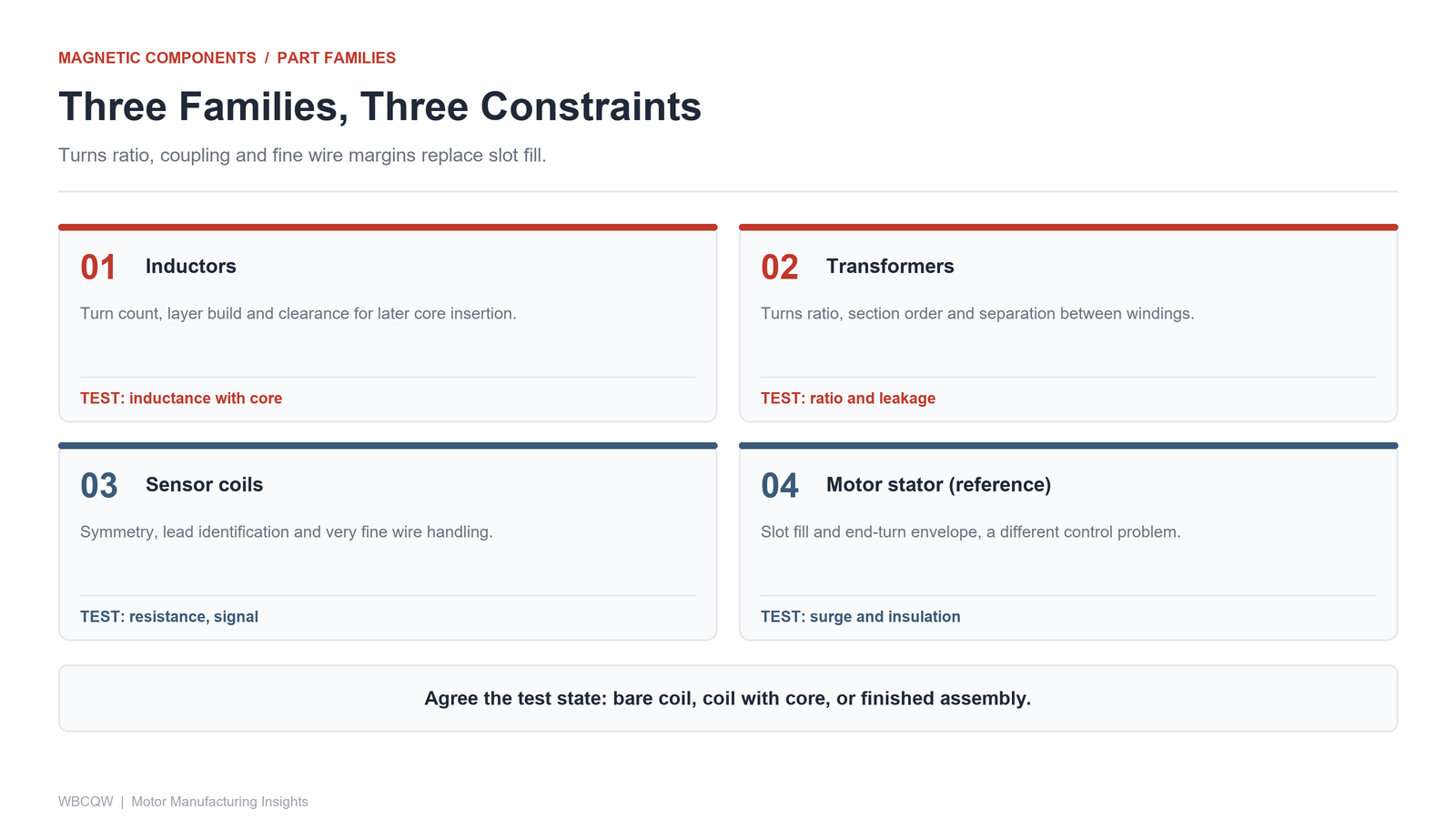
Fig. 1 - Three families of wound magnetic parts, each with a different controlling constraint. Illustrative diagram, not a product photograph.
Fine wire and insulation margins
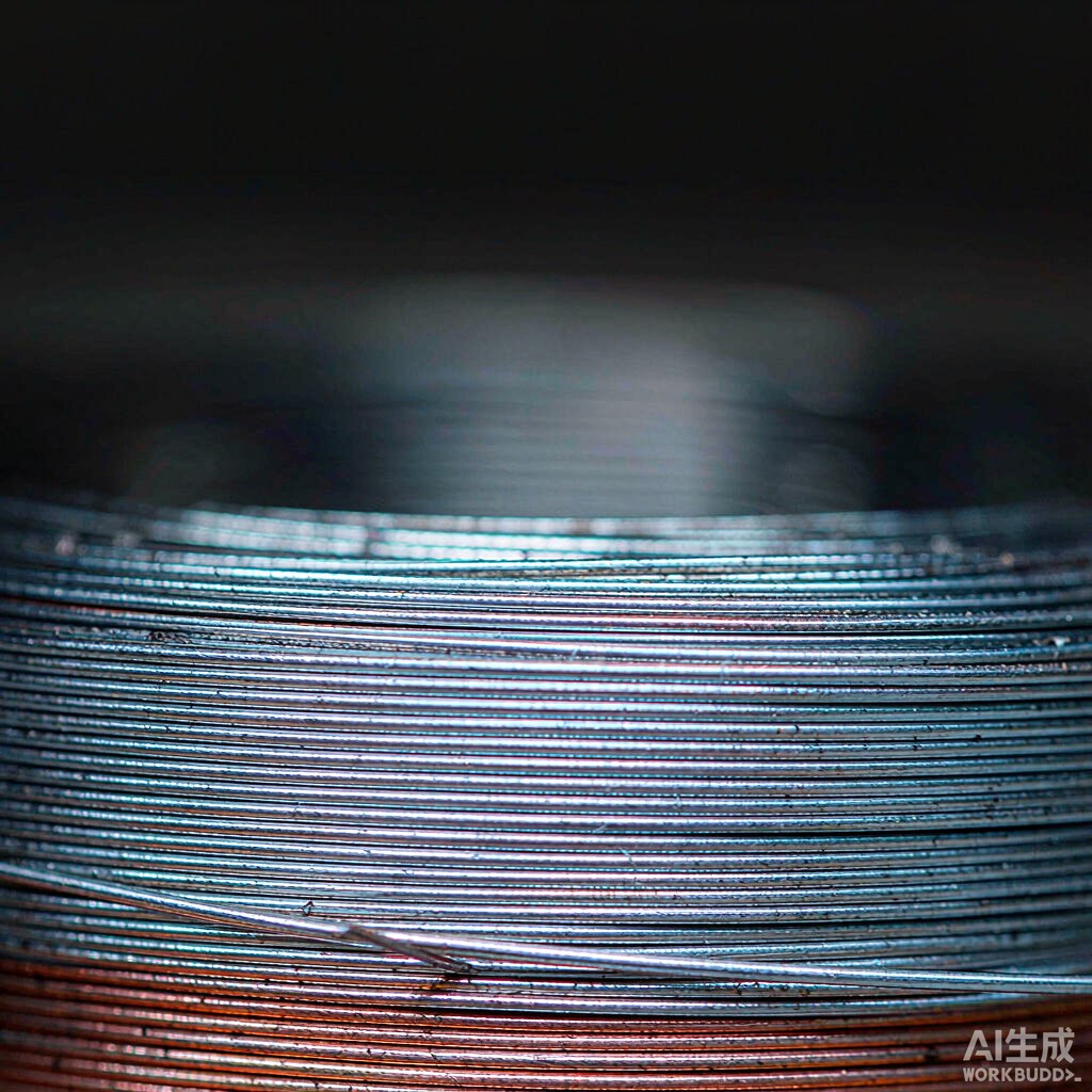
Many magnetic components use wire much finer than a traction motor stator, which changes the entire tension and hardware discussion. The tension window is narrow, guides and nozzles must be matched to the diameter, and the enamel is more easily damaged by a small burr or an excessive bending radius. Start-up and traverse reversal peaks, rather than the steady setpoint, are usually what decide whether the wire survives. A full-cycle tension trace or a documented gauge check is more useful than a single nominal value.
Insulation margins between windings, between layers and to the core need their own evidence: material data, any interlayer insulation or margin tape used, and the electrical test method for the finished part. Describe the termination method as well, because stripping, soldering or welding a fine conductor can damage enamel adjacent to the joint. Where the design uses a margin or a specific creepage distance, make it a dimensional check on the wound part, not only a drawing note.
Where stator winding equipment does not fit
A machine optimised for stators is built around a certain part size, wire diameter range, tooling envelope and test regime. It may not accept a small bobbin, may lack the resolution to control very fine wire tension, or may be unable to place multiple windings with the required section geometry. Multi-axis motion helps with access, but it does not replace a matched wire path, a suitable fixture and an appropriate test setup.
Be explicit about the boundary in the enquiry. If the supplier's equipment is primarily for round-wire stators, ask which parts of your requirement it can meet, which need different tooling, and which fall outside its scope altogether. A candid answer with a sample run is more valuable than a universal claim. This is also where a fine wire breakage checklist becomes relevant: if a proposed setup produces peaks the conductor cannot tolerate, no amount of programming will make it production-ready.
| Component | Winding constraint | Test method |
|---|---|---|
| Power or signal inductor | Turn count, layer build, core clearance | Inductance in the stated core state, resistance |
| Small transformer | Turns ratio, section order, separation | Ratio and leakage measurement, insulation test |
| Sensor coil | Symmetry, lead identification, fine wire handling | Resistance at stated temperature, signal check |
| Motor stator (reference) | Slot fill, end-turn envelope | Surge, insulation, resistance, dimensions |
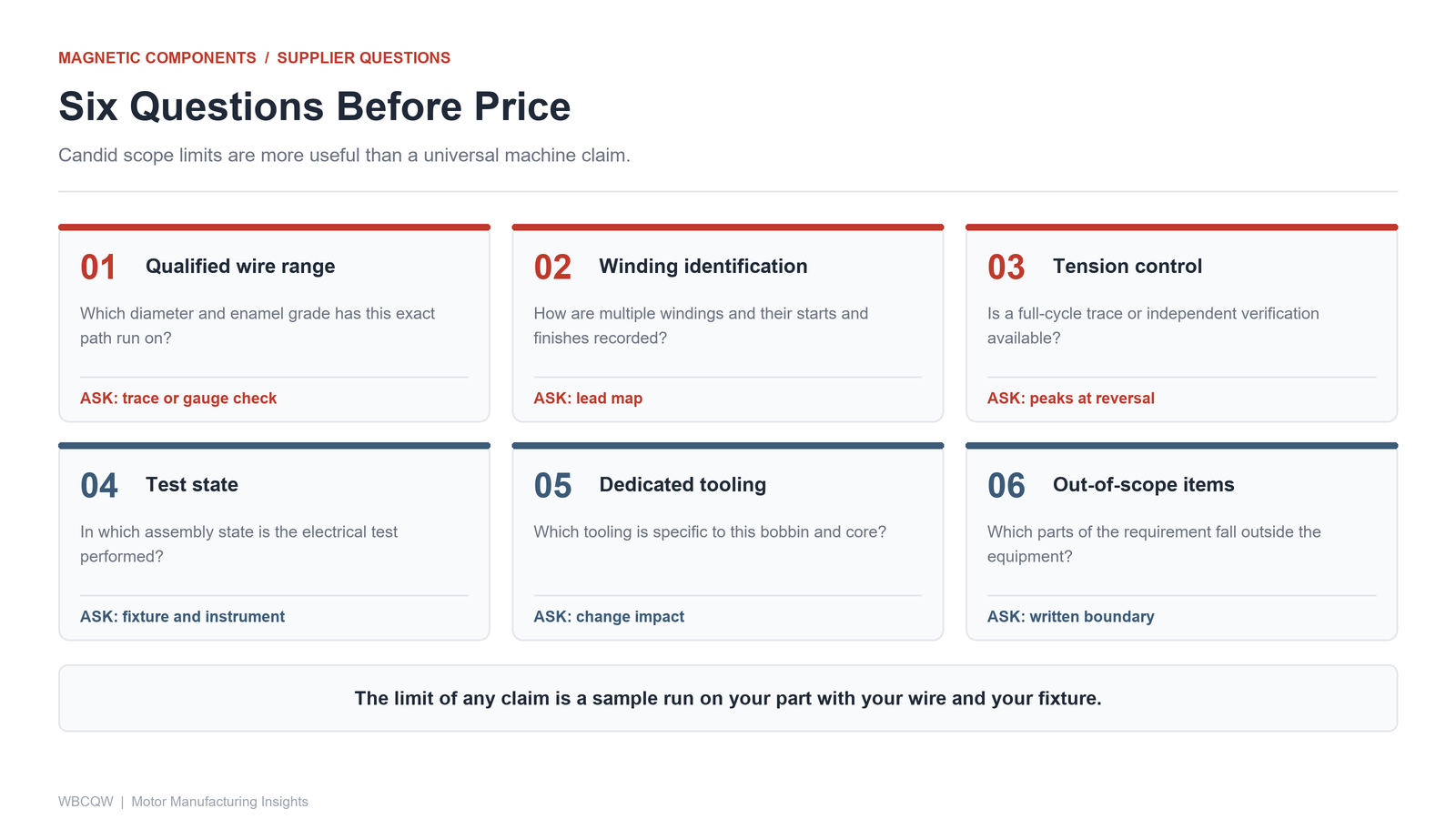
Fig. 2 - Six questions that separate a suitable winding process from a generic machine claim. Illustrative diagram, not a product photograph.
A supplier question list for magnetic parts
Ask six questions before discussing price. Which wire diameter and enamel grade has this exact wire path been qualified on? How are multiple windings and their start and finish leads identified? What is the tension control method, and can a full-cycle trace or gauge verification be provided for your wire? In which assembly state is the electrical test performed, and with which instrument? Which tooling is specific to your bobbin, and what happens if the core is changed? Finally, which parts of the requirement does the supplier consider outside the machine's scope?
Xingte Technology, based in Shenzhen, supplies multi-axis precision winding machines, stator and rotor winding machines, and standard and customized automation solutions for automotive electronics, robotics, UAV and optical module production, with sample testing, on-site commissioning and after-sales support. Keep that scope in mind when qualifying a magnetic component: round-wire capability and customization experience are useful, but they are not evidence that a given bobbin, core and test regime have been validated. The limit of any equipment claim is the sample run on your own part, with your wire lot and your test fixture, followed by a written baseline that both sides can reproduce.