A traction motor design brief is written in the language of efficiency, torque density, thermal limits, insulation coordination and noise. A winding process is specified in tension, pitch, turn count and test results. The two documents are connected, but the translation is rarely written down, which is why a winding supplier can meet every line of a process specification and still deliver a stator that the motor designer rejects. This article works backwards from motor-level targets to the winding characteristics and measurements that support them. It is a requirements article, not a comparison of how to verify machine accuracy or of production routes.
What the motor designer optimises for
Designers balance several targets at once. Higher efficiency pushes toward more copper in the slot and shorter end turns. Higher torque density raises current and therefore heat. A higher DC-link voltage increases the electrical stress on insulation. Packaging constraints limit the end-turn envelope, while NVH and balance targets constrain how uniformly the winding can be built. Each target pulls on the others, so a winding requirement should always state which target it serves.
This is also where a specification becomes testable. "Good slot fill" is a design intention; a defined fill range measured on a sectioned stator, with a stated method, is a requirement. Ask for the motor-level target and the reason behind it before accepting a process number. A winding parameter copied from a previous program may have been optimised for a different voltage class or cooling concept.
Slot fill and copper loss
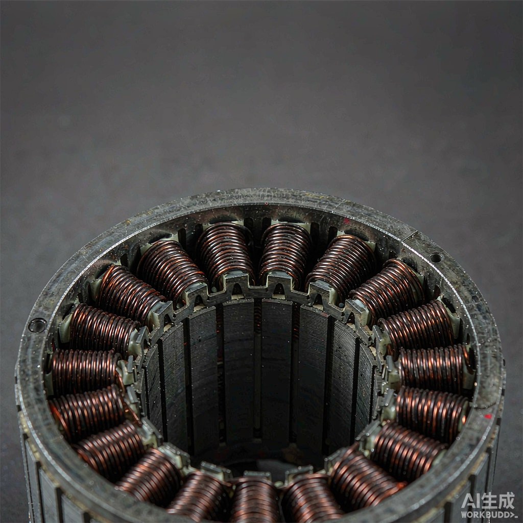
Copper loss scales with resistance, and resistance falls when more conductor cross-section fits in the available slot. That makes slot fill one of the strongest links between winding and efficiency. But fill is an outcome, not a machine setting: it depends on conductor diameter, enamel thickness, turn placement, layer build and the insulation liner occupying part of the slot. Pushing placement too aggressively to gain a little fill can damage the enamel or make insertion and closing operations unreliable.
Ask how fill is measured and on how many stators, and require a section or imaging evidence rather than a calculated value alone. Also ask for the resistance distribution across produced parts at a stated temperature and soak time. A mean that looks acceptable can hide a spread caused by inconsistent turn placement or wire lot variation. Where the design uses a formed conductor instead of round wire, the entire measurement chain changes, and a round-wire process cannot be used as evidence for it.
Insulation stress at higher DC link voltage
As platform voltage rises, the insulation system has less margin against transient overvoltage and partial discharge. The winding process influences that margin in ordinary ways: a guide with a worn groove, a tight bending radius, a sharp slot edge or a lead dressed against a laminated edge can all reduce the effective insulation without changing any electrical test result on a new part. That is why process evidence belongs in the insulation discussion, not only material certificates.
Request the stator-level test method, including surge and insulation measurements, the conditions, the pass criteria and how failures are classified. A wire certificate alone describes the conductor before it was wound; it says nothing about what happened to the enamel during placement. For a higher-voltage program, ask that the sample test use the real slot insulation, the real lead routing and the real termination, because those are the locations where the margin is actually consumed.
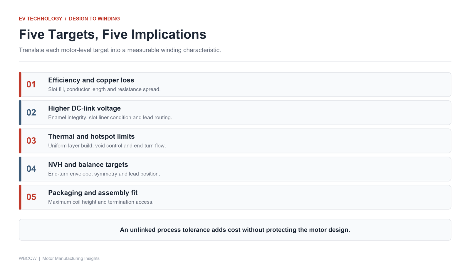
Fig. 1 - Five motor-level targets and the winding characteristic each one controls. Illustrative diagram, not a product photograph.
Thermal paths and hotspot limits
Heat leaves the winding through the slot liner, the laminations and the cooling system, so the geometry of the coil affects the thermal path. Voids between turns, uneven layer build or an end turn that blocks coolant flow can create a local hotspot even when total copper loss is on target. A winding that packs tightly but inconsistently may therefore be worse thermally than a slightly looser but uniform one.
Ask which thermal evidence the motor team will use and how winding variation feeds into it: temperature rise tests, embedded sensors or a validated model with stated assumptions. Tie that back to a process control: if layer build or end-turn height is the variable, define how it is measured on production parts and how often. Note the boundary clearly, though. Winding consistency can protect a thermal design; it cannot compensate for an inadequate cooling concept.
NVH, balance and end-turn shape
Noise and vibration targets introduce geometric requirements that electrical tests do not capture. Uneven end turns, asymmetric lead routing and mass imbalance all affect the assembled rotor-stator system. A stator can pass resistance, surge and insulation tests and still contribute to a balance or NVH problem at vehicle level. End-turn envelope, lead position and the repeatability of the winding build should therefore be treated as dimensions, with a measurement method and a control plan.
Ask for dimensional data on a defined sample of production parts, not just the first article. Where the design allows impregnation or a resin step, agree whether measurements are taken before or after it. A winding requirement that omits the post-process state can be met in the winding cell and lost in the next operation.
| Motor requirement | Winding implication | Measurement |
|---|---|---|
| High efficiency and low copper loss | Slot fill, conductor length, resistance spread | Sectioned stator, resistance at stated temperature |
| Higher DC-link voltage capability | Enamel integrity, slot liner, lead routing | Stator-level surge and insulation test with conditions |
| Thermal and hotspot limits | Uniform layer build, void control, end-turn flow | Temperature rise test, dimensional data on samples |
| NVH and balance targets | End-turn envelope, symmetry, lead position | Dimensional inspection across production parts |
| Packaging and assembly fit | Maximum coil height, termination access | Gauge or assembly trial after the final process step |
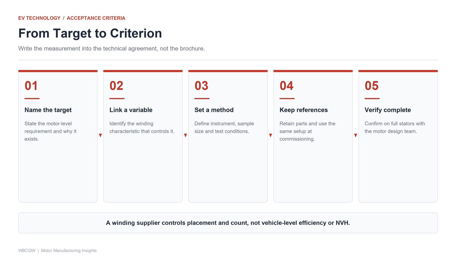
Fig. 2 - Turn each motor target into a measurable winding criterion before the request for quotation. Illustrative diagram, not a product photograph.
Translating motor specs into winding acceptance criteria
Build a two-column translation table with the motor team: on the left, the design target and its test; on the right, the winding characteristic, the measurement method, the sample size and the conditions. Keep the same instrument and reference parts for the sample test and for commissioning. Where a target cannot be linked to a measurable winding characteristic, say so rather than inventing a tighter process tolerance; an unlinked tolerance adds cost without protecting the design.
Xingte Technology, based in Shenzhen, supplies multi-axis precision winding machines, stator and rotor winding machines, and standard and customized automation solutions for automotive electronics, robotics, UAV and optical module production, with sample testing, on-site commissioning and after-sales support. Its round-wire precision winding equipment is one part of this chain, not the whole motor. The honest boundary is that a winding supplier can control placement, count and enamel integrity, but cannot guarantee vehicle-level efficiency, thermal or NVH results. Those depend on the motor design, the insulation system and the assembly process, and must be verified by the motor team on complete stators.