Hairpin stators and round-wire stators are often discussed as if one were an upgrade of the other. They are not. They are two different conductor systems built on two different production lines, with different forming steps, joining methods, insulation risks and test strategies. Buying a hairpin line is not a matter of adding a module to a conventional winder, and a round-wire machine cannot be tuned into one. This comparison sets out where the routes diverge, what evidence to request for each, and how to choose by product volume, variant mix and service capability rather than by a headline efficiency figure.
Two winding routes, two production lines
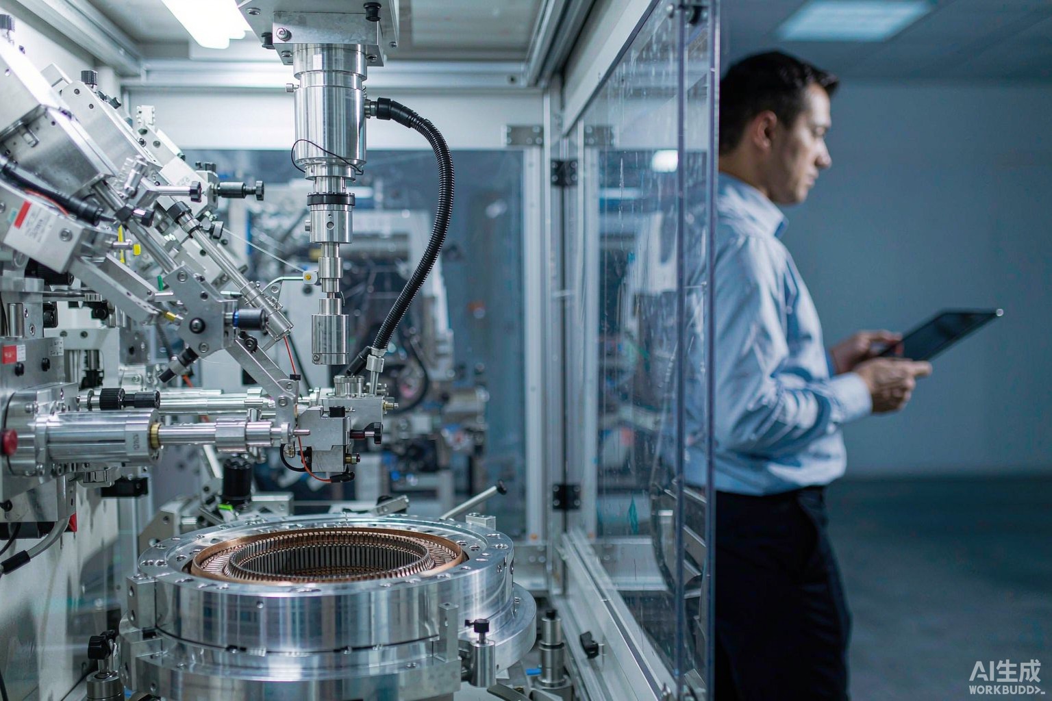
A round-wire line feeds continuous enameled wire from a spool through a tensioner and guide, placing turns one after another into a slot or onto a bobbin. The process is flexible: changing turn count or wire diameter is largely a program and wire-path change. A hairpin line cuts rectangular conductors to length, strips the enamel at the ends, forms each conductor into a U shape, inserts the pins into the stator slots, twists and welds the ends, then insulates and tests the joints. Most of those stations have no counterpart on a round-wire machine.
That structural difference drives the business case. Hairpin equipment is capital intensive and rewards high volumes of a small number of stator variants, where a large conductor cross-section raises slot fill. Round-wire equipment suits mixed production, frequent changeovers and a wide range of coil geometries. Our guide to evaluating winding machine accuracy covers how to verify the round-wire route with your own parts; that verification logic does not transfer to hairpin forming and welding.
Conductor forming and insertion
On a hairpin line, the critical variables are cut length, strip quality, bend radius, springback and insertion force. A forming error creates a pin that will not seat, or that seats while damaging the slot liner. Insertion is a multi-pin operation with tight positional tolerance; a single misaligned conductor can distort the end-turn bundle. Ask for dimensional data on formed pins and for insertion force traces, not just a photograph of a finished stator.
On a round-wire line, the equivalent variables are tension behaviour, traverse pitch, layer transitions and the bend radii in the wire path. Fine wire fails at momentary peaks, so the tension trace over a full cycle matters more than the nominal setting; see our fine wire breakage troubleshooting guide. Both routes depend on clean, controlled conductor handling, but the failure modes and the instruments used to detect them are entirely different.
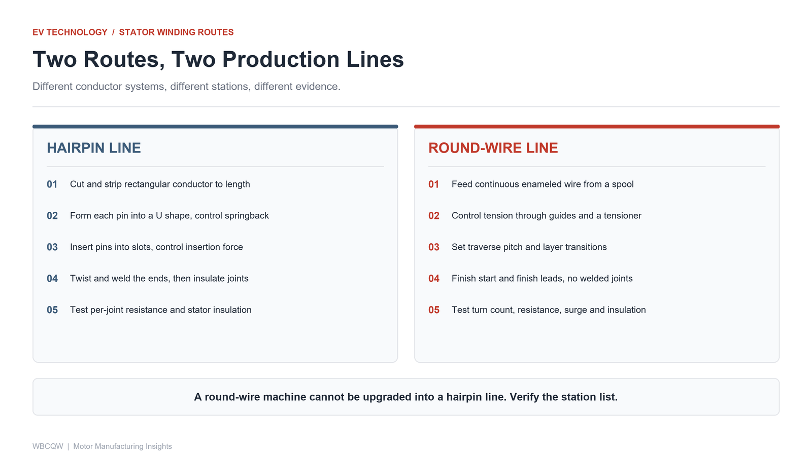
Fig. 1 - Two conductor systems, two station chains. A round-wire line cannot be upgraded into a hairpin line. Illustrative diagram, not a product photograph.
Insulation stress at higher voltage
Higher DC link voltages and fast-switching inverters increase electrical stress on turn-to-turn and phase-to-phase insulation. Hairpin conductors have a rectangular cross-section and relatively few turns, so the voltage per turn can be high and the enamel at formed bends is mechanically stressed before the machine ever runs. Slot liners, end-turn separation and the insulation applied after welding become the critical controls.
Round-wire stators have many more turns and many more inter-turn contacts, so the concern is distributed: enamel continuity, layer crossover pressure and the risk of scuffing during winding. Neither route is inherently safer. What matters is whether the supplier can show insulation and surge test results on the actual stator design, with the test voltage, waveform and pass criteria stated. A generic insulation certificate for the wire is not a stator-level test.
Joining, welding and testing
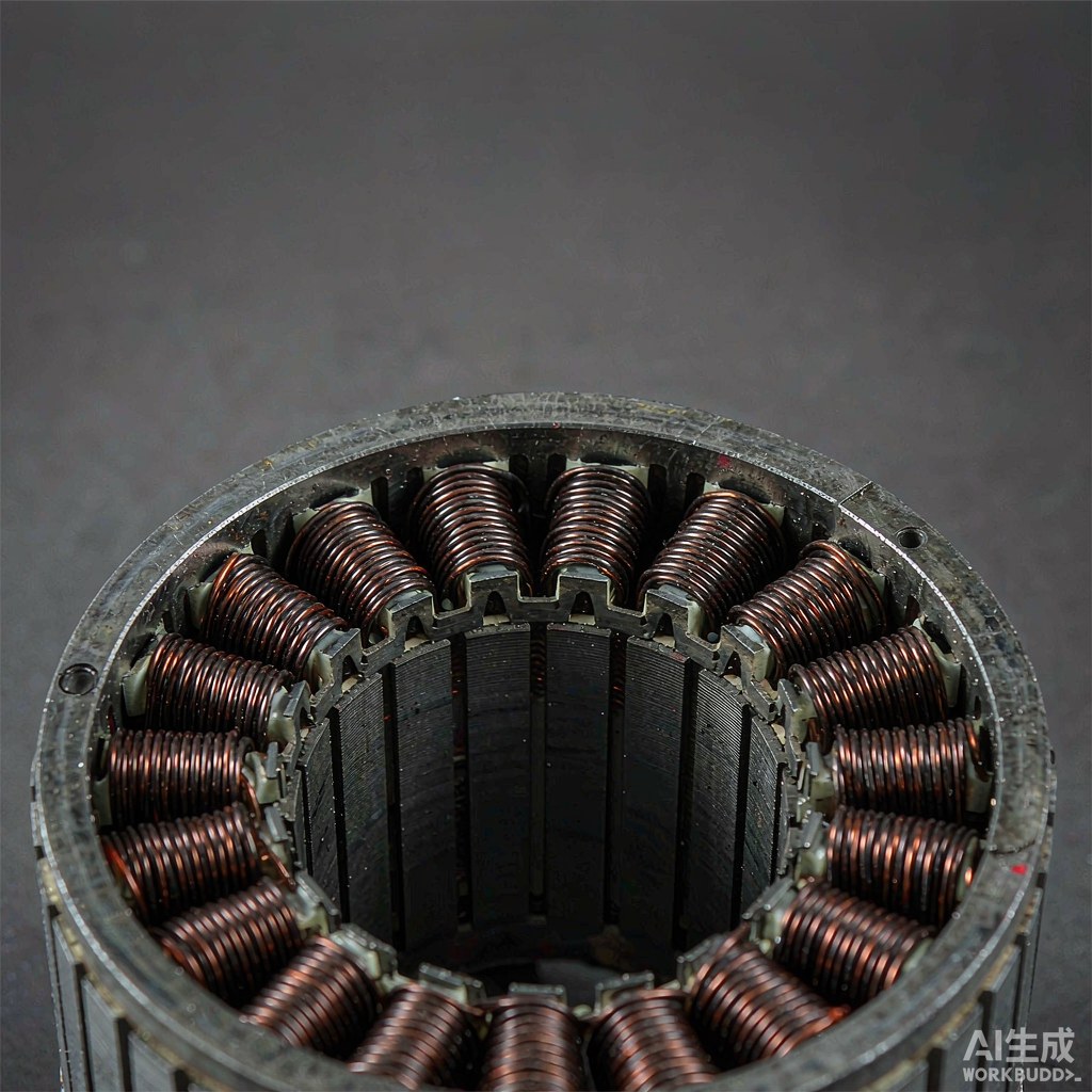
Hairpin stators replace a continuous wire with hundreds of welded joints. Each joint adds a resistance point and a potential reliability risk, so the line needs stripping quality control, welding parameter monitoring, and inspection of twist and weld geometry. Resistance and partial discharge testing on the finished stator are part of the production flow, not just a laboratory check. Traceability usually extends to individual welding parameters per joint.
Round-wire coils have continuous conductors with start and finish leads. Testing focuses on turn count, resistance, insulation and surge behaviour, and on placement quality. The acceptance evidence is therefore a distribution over many parts, not a per-joint record. When comparing suppliers, ask which measurements are taken on every part, which are sampled, and who owns the data. That question exposes the real cost of quality more reliably than a machine specification sheet.
What a round-wire line can and cannot do
Xingte Technology, based in Shenzhen, supplies multi-axis precision winding machines, stator and rotor winding machines, and standard and customized automation solutions, serving automotive electronics, robotics, UAV and optical module production with sample testing, on-site commissioning and after-sales support. That equipment belongs to the continuous round-wire route: it is built for precision placement, controlled tension and programmable winding patterns, not for cutting, forming, inserting and welding rectangular hairpin conductors.
Stating that boundary plainly protects both sides. A supplier claiming one platform covers both routes should be asked to show the forming, stripping, insertion and welding stations, plus stator-level test data for each. Equally, a round-wire line is not the inferior choice: for low to medium volumes, high variant counts, fine wire, or coils outside a traction stator, its flexibility is often the deciding advantage. Accuracy and cycle time still trade off on either route, and neither machine compensates for a winding design that pushes the conductor beyond its mechanical margin.
Choosing by volume, variant mix and service capability
| Dimension | Hairpin line | Round-wire line | Evidence to request |
|---|---|---|---|
| Conductor | Cut and formed rectangular pins | Continuous enameled round wire | Formed-pin dimensional report; wire lot certificates |
| Key stations | Strip, form, insert, twist, weld | Tension, traverse, layer control | Station list and layout drawing |
| Joining | Hundreds of welded joints | Continuous conductor, two leads | Weld parameters and joint inspection records |
| Insulation focus | Bends, slot liner, post-weld insulation | Enamel continuity, crossover pressure | Stator-level surge and insulation test method |
| Best fit | High volume, few variants | Mixed variants, fine wire, frequent changeover | Changeover time measured on your parts |
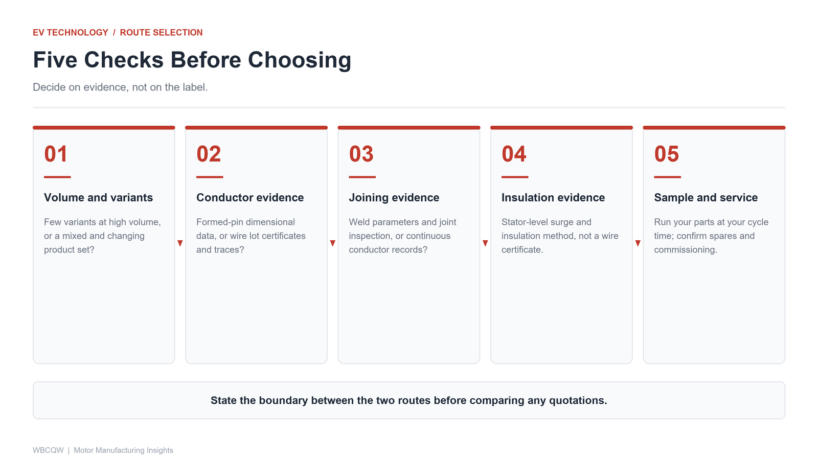
Fig. 2 - Five checks that turn a route comparison into a purchasable requirement. Illustrative diagram, not a product photograph.
Decide on the evidence, not the label. Ask each candidate to run a sample with your conductor, stator geometry and target cycle time, and to state which stations, joints and tests belong to the quoted scope. If the choice is hairpin, verify the welding and insulation evidence chain. If it is round wire, verify tension behaviour and placement over a continuous run. The two routes answer different production questions, and a clear boundary between them is more useful than a claim that one machine does everything.