A batch of coils measures within resistance limits on Monday and sits at the edge of the window on Thursday, with no program change and no obvious fault. The first instinct is to adjust the winding machine. That is usually the wrong move. Coil resistance is a function of wire length, wire cross-section, temperature and the measurement circuit, so a drift can originate in the wire lot, the test fixture, the ambient conditions or the process. This map separates false alarms from real process shifts and gives a five-step investigation that produces records a supplier can act on.
When resistance drift is a process signal
Resistance rises when the conductor gets longer, thinner, hotter or more resistive at its contacts. In winding terms that means more turns, a smaller effective wire diameter, a higher copper temperature at measurement, or a poor connection in the test leads. A genuine process shift tends to move the whole batch mean and show a pattern: it tracks a wire lot, a program revision, a spool change, a shift or a machine. Random scatter around a stable mean is more often a measurement problem.
Record the shape of the change before troubleshooting. Plot resistance by part sequence, note the wire lot, spool, program version, operator and ambient temperature, and mark where the mean moves. A step change at a lot boundary and a slow ramp across a shift point to completely different causes. Our accuracy acceptance guide explains how to define the measurement conditions and baseline that make this plot meaningful in the first place.
Measurement conditions that create false alarms
Copper resistance changes appreciably with temperature, so a coil measured straight after winding or near a warm machine will read higher than the same coil after stabilising in a controlled room. Standardise a soak time and a reference temperature, and either correct the reading or record the temperature with every result. Check the test fixture next: two-wire measurements on low-resistance coils include lead and contact resistance, which can drift as probes wear, oxidise or lose contact pressure.
Verify the instrument with a stable reference part before blaming the process. Re-measure a retained sample from the good batch at the start of each shift. If the reference has moved too, the fault is in the measurement chain. Also check that the start and finish leads are trimmed to the same length and clamped at the same point; a few millimetres of extra lead or a different clamp position changes the reading on small coils.
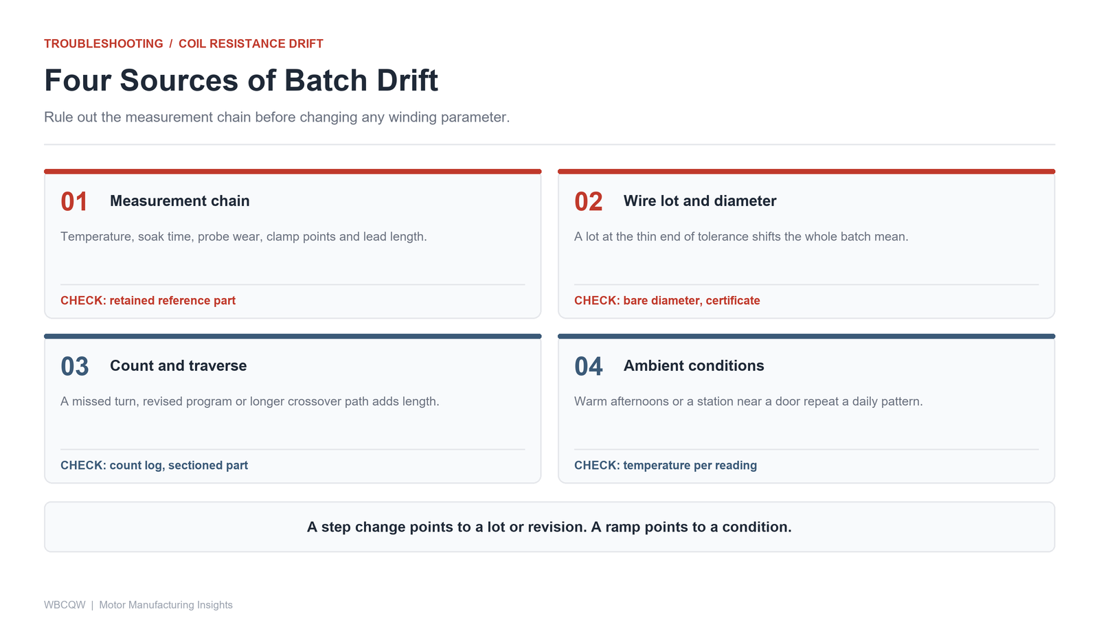
Fig. 1 - Four sources of drift. Rule out the measurement chain before changing any winding parameter. Illustrative diagram, not a product photograph.
Wire lot and diameter tolerance
Enameled wire is supplied within a diameter tolerance, and resistance is inversely proportional to conductor cross-section. A lot sitting at the thin end of its allowed range can shift the batch mean by enough to consume most of a tight resistance window, with perfectly correct turn count and tension. Enamel thickness also varies, which changes the effective conductor diameter while the outside diameter looks normal.
Ask for the lot certificate and measure bare conductor diameter yourself on samples from each lot, after removing the enamel with a method that does not attack the copper. Keep resistance results by lot, not just by date. If the drift follows the lot, take the diameter data and the resistance plot to the wire supplier; reprogramming the winder to compensate would only hide a material variation that will return on the next lot.
Turn count and traverse errors
If the mean moves by roughly the resistance of one turn, suspect turn count. A miscounted turn can come from a program revision, a changed start or finish lead allowance, or a sensor that occasionally misses an index pulse. Modern machines usually log the commanded turn count, so compare the log against the program revision rather than relying on the operator's recollection.
Traverse errors change wire length without changing the commanded count. A wrong pitch, a layer-end crossover that adds a partial turn, or a build-up that forces the wire into a longer path all increase length. The giveaway is that resistance drifts together with a dimensional change: coil height, end-turn shape or layer profile. Inspect placement on a sectioned sample and compare the physical layer count with the program. Fine wire breakage and placement faults share some of these root causes, but the diagnostic target differs; our fine wire breakage guide covers the breakage path specifically.
Temperature, contact resistance and test fixtures
Separate the three thermal and contact effects with a simple controlled experiment. Measure one retained coil repeatedly at the same temperature with the same fixture; then change only the fixture, then only the ambient condition. Use a four-wire method where resistance is low enough for lead resistance to matter, and log probe cleaning and replacement as maintenance events rather than informal habits.
Watch for seasonal and shift patterns: a workshop that is warmer in the afternoon, or a test station near a door, can produce a convincing "process drift" that repeats every day. If the drift follows ambient temperature and disappears on a temperature-corrected plot, fix the measurement environment instead of the machine. Xingte Technology, based in Shenzhen, supplies multi-axis precision winding machines, stator and rotor winding machines, and standard and customized automation solutions, with sample testing, on-site commissioning and after-sales support. Traceable process data makes this kind of comparison possible, but no machine can compensate for an uncontrolled test setup or an incoming wire lot outside its specified range.
A five-step drift investigation
Freeze the measurement chain. Verify the instrument with a reference part, fix soak time, temperature, clamp points and lead length, then re-measure retained samples from the good batch.
Plot the drift. Sequence the results by part, and mark lot changes, spool changes, program revisions, operators and shifts. Identify whether the change is a step, a ramp or extra scatter.
Verify the conductor. Measure bare diameter from each lot, review certificates, and check whether the resistance shift follows the material.
Check count and geometry. Compare commanded turn count logs with the program revision; inspect layer count, coil height and end-turn shape on a sectioned sample.
Sign off with a controlled baseline. Agree a resistance window with a stated temperature and method, keep reference parts and control charts, and require a repeat measurement at commissioning before accepting a new setup.
| Symptom | Likely cause | First check | Record to keep |
|---|---|---|---|
| Reference part also moved | Instrument or fixture | Calibration, probe wear, clamp pressure | Reference control chart |
| Step change at a lot boundary | Wire diameter or enamel build | Bare diameter and lot certificate | Resistance by lot |
| Shift equals about one turn | Turn count or program revision | Commanded count log versus program | Revision history |
| Drift with coil height change | Traverse pitch or layer crossover | Sectioned sample, layer count | Dimensional and resistance pair |
| Follows time of day | Ambient temperature | Soak time and temperature correction | Temperature log per reading |
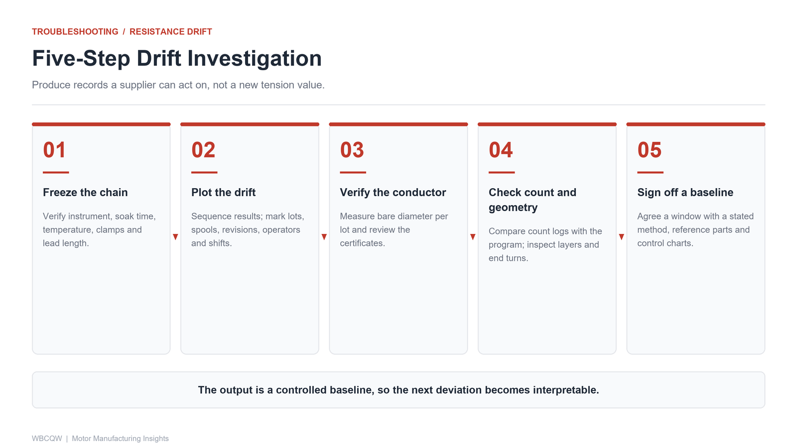
Fig. 2 - Five steps from a frozen measurement chain to a controlled baseline. Illustrative diagram, not a product photograph.
Resistance drift is a system property, not a machine setting. Rule out the measurement chain first, then the conductor, then the program and geometry, and only then consider adjusting the process. The output of the investigation should be a controlled baseline with a stated method, reference parts and a control chart, not a new tension value written into a setup sheet. That baseline is what makes the next deviation interpretable.