A new winding program almost never fails in steady state. It fails in the first twenty turns, at the first layer crossover, or during the first acceleration to production speed. Setting up a program is therefore a sequence of small, recorded decisions rather than a single parameter entry. This tutorial walks from the physical part to a signed first article, and stops short of acceptance testing: how to define and verify machine accuracy before purchase is covered separately in our guide to evaluating stator winding machine accuracy.
Prepare the bobbin, wire and program
Start with the part, not the screen. Confirm the bobbin or stator drawing revision, flange geometry, slot or winding window dimensions, winding direction and lead exit positions. Check that the sample parts come from the same tooling as production parts; a prototype bobbin with slightly different flange radius will produce a program that cannot be transferred. Measure and record the bare wire diameter and the enamel grade from the actual spool, because a lot at the thin end of tolerance changes both packing and resistance.
Before entering any numbers, give the program a name that encodes part number, wire lot, revision and date, and save an empty copy. Verify that the spindle, traverse and tensioner are at their home positions and that the wire path contains no sharp edge. A dry run without wire, at low speed, confirms that the traverse will not collide with the fixture. Most commissioning delays trace back to a fixture or a drawing revision that was never written into the program header.
Set the tension path before the first turn
Tension is a path property, not a single setting. Thread the wire through guides, the tensioner and the nozzle with the same number of wrap angles you intend to use in production, then set a deliberately low starting value and turn the spindle by hand. Watch the wire at the guide exits: any visible sawing, chatter or slack take-up tells you the path is wrong before a sensor does. Increase the setpoint in small steps while observing the wire, not the display alone.
The number that matters is the peak, not the average. Start-up, deceleration and traverse reversal all produce transient loads that a steady-state reading hides. If the machine offers a recorded tension trace, capture a full cycle at the intended speed and keep it with the setup sheet. If it does not, plan a periodic manual check with a handheld gauge at the same point in the path. Fine wire breaks at peaks, and our root-cause checklist for wire breakage explains why those peaks are so often misdiagnosed as bad material.
Define traverse and layer transitions
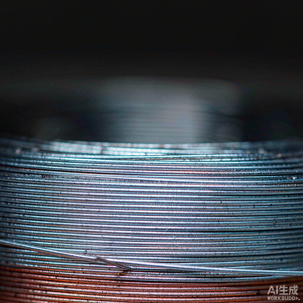
Set traverse pitch in millimetres per spindle revolution, not as a feed rate. A pitch equal to the wire diameter gives theoretical close packing, but real enamel thickness, guide compliance and tension all shift the practical value. Define the start point, the end point and the reversal dwell, then run a single layer and inspect it under magnification before adding a second. Gaps, overlaps or a ridge at the reversal are geometry problems; increasing tension to hide them usually creates a breakage problem later.
Layer transitions deserve their own parameters. Decide how the wire climbs onto the next layer, where the crossover sits, and whether an interlayer sheet or a changed pitch is required. Record the number of turns per layer and the total turns, then verify the program against the drawing rather than against the previous part. A copied program with one inherited reversal point can produce a coil that passes a turn-count check and still fails an insulation or fit check at assembly.
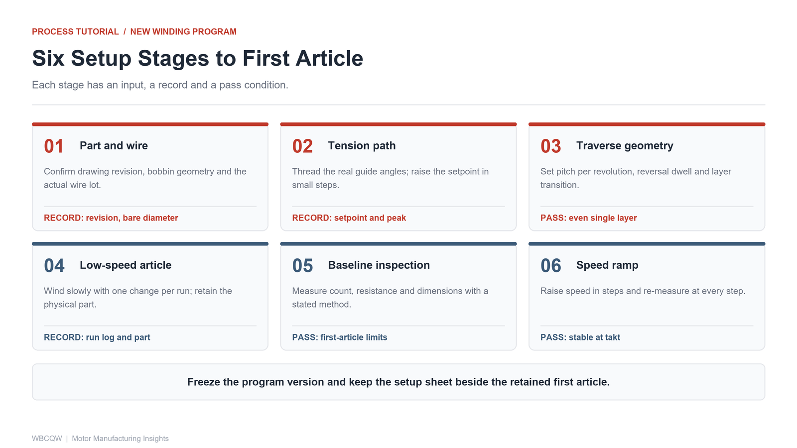
Fig. 1 - Six setup stages, each with an input, a record and a pass condition. Illustrative diagram, not a product photograph.
Run a low-speed first article
Wind the first article at a fraction of the intended speed with an operator at the stop button. The aim is not output but observability: listen for changes at the reversal, watch the wire entering the nozzle, and stop immediately if a turn climbs out of its lane. Keep the first article physically, even if it is imperfect, and label it with the program revision and wire lot.
Do not correct three things at once. If the layer shows a ridge, change the reversal geometry and rerun; if the wire chatters, revisit the path and tension. A log that records one change per run is what makes the eventual setup reproducible. Programs tuned by several simultaneous adjustments often cannot be restarted after a spool change, which is the clearest sign that the process was never actually under control.
Inspect and record the baseline
Inspect the first article against a short, written list: turn count, resistance with a stated soak time and temperature, coil dimensions, lead length and exit position, layer appearance, and any visual damage to the enamel. Measure resistance only after the part has reached the same temperature as the reference, and always clamp at the same points. Record the instrument used and keep the reference part; without a retained sample, a later drift cannot be separated from a measurement change.
Write the baseline into the setup sheet: program revision, wire lot, tension setpoint and peak, traverse pitch, reversal dwell, speed, ambient conditions and measured results. This sheet is the first-article approval. It is also the input to any later troubleshooting, because it defines what "normal" looked like on the day the program was accepted.
| Step | Input to set | What to record | Pass condition |
|---|---|---|---|
| Part and wire check | Drawing revision, wire lot | Part number, bare diameter, enamel grade | Matches the program header |
| Tension path | Guide angles, setpoint | Setpoint, peak, trace or gauge reading | No chatter, slack or visible damage |
| Traverse geometry | Pitch, reversal, dwell | Turns per layer, crossover position | Even single layer, no ridge |
| Low-speed article | Reduced speed, one change per run | Run log and retained part | Stable placement through reversal |
| Baseline inspection | Test method and conditions | Count, resistance, dimensions, photos | Within the agreed first-article limits |
| Speed ramp | Speed steps and hold time | Results at each step | No drift at target cycle time |
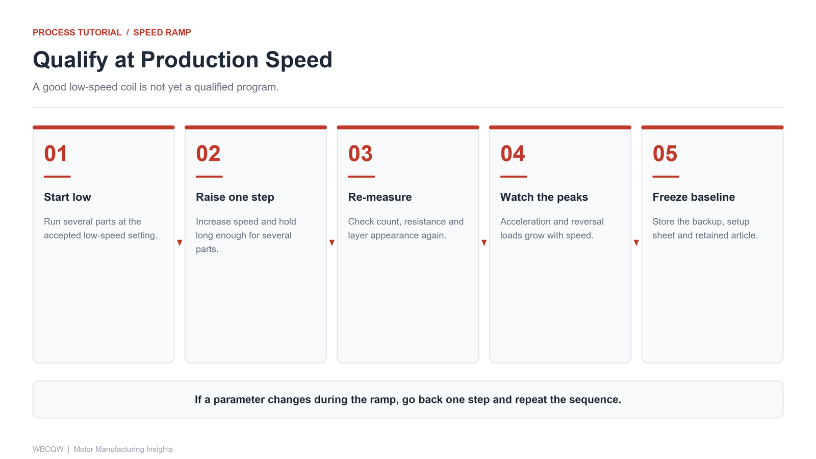
Fig. 2 - Ramp speed in steps and re-measure at each step; a program that holds at low speed may not hold at takt. Illustrative diagram, not a product photograph.
Ramp to production speed in steps
A program that produces a good coil at low speed has not yet been qualified for production. Raise speed in planned steps, holding each step long enough to wind several parts, and re-measure count, resistance and layer appearance at every step. Acceleration and deceleration peaks grow with speed, so a tension setting that was gentle during the first article can become marginal at takt. If a parameter has to be changed during the ramp, return one step and repeat the measurement sequence.
Finish by freezing the program version, storing the backup where a second person can restore it, and recording the final setup sheet beside the retained first article. Xingte Technology, based in Shenzhen, supplies multi-axis precision winding machines, stator and rotor winding machines, and standard and customized automation solutions for automotive electronics, robotics, UAV and optical module production, with sample testing, on-site commissioning and after-sales support. Whatever the machine, the limits of this procedure are worth stating: a clean first article proves that one part, on one wire lot, under one set of conditions, was wound correctly. It does not prove capability across lots, shifts or seasons. That evidence comes from repeated runs and a controlled baseline, not from a single successful setup.