Machine comparisons usually start and end with winding performance, yet two systems that wind equally well can ask very different things of a building. One may need a larger service envelope, a cleaner air supply, a stiffer floor or a wider access route than the other. Those demands are easy to overlook during selection and expensive to discover after delivery, when the layout is already fixed. Putting site requirements into the comparison sheet keeps the decision from being quietly revised by the factory. Our guide to planning a winding cell layout covers the spatial side; this article converts footprint, power, air, environment and access into a comparable specification. The aim is a purchase choice that still holds on the day the crate arrives.
Why site requirements belong in the technical comparison
A machine is not just a set of axes and a controller; it is a load on a building and on a schedule of services. Power, compressed air, floor capacity, ambient limits and access all have to be met before the machine can run, and meeting them has a cost that belongs in the total decision. Leaving these out of the comparison makes two machines look more alike than they are.
Footprint is more than the machine outline
The outline in a brochure is the machine body, not the space it occupies in service. The real footprint includes door swing, guard clearance, the operator working position, the wire and bobbin supply, the finished-part take-off, and the room a technician needs to reach a panel. A layout drawn only to the machine outline tends to collide with a column, a neighbouring cell or an aisle.
Ask for an installation drawing with service and maintenance envelopes, not just a plan of the base. Mark the direction of material flow and the position of the operator, then check the drawing against the actual floor, including overhead obstructions and cable routes. A compact machine that needs clearance on all four sides can consume more usable area than a larger one designed for a wall or a line. Our note on verifying machine accuracy before purchase is a reminder to confirm every dimension on the real site.
Electrical supply and air quality at the point of use
Electrical requirements are more than a total power figure. Record the supply configuration, the connection type, the protection and isolation expected, and any need for a stable or conditioned supply. Note the inrush and the earthing arrangement, and confirm who provides the feeder and the disconnect. A machine specified against one supply assumption may need a transformer or a dedicated circuit at the point of use.
Compressed air is the most commonly understated utility. Specify the required pressure, flow, and crucially the quality: dry, filtered air free of oil and condensate at the point of use, not just at the compressor. Pneumatic tensioners, nozzles and grippers are sensitive to moisture and pressure fluctuation, and a central line that serves other equipment may not hold a steady supply under load. Confirm the treatment equipment and who maintains it.
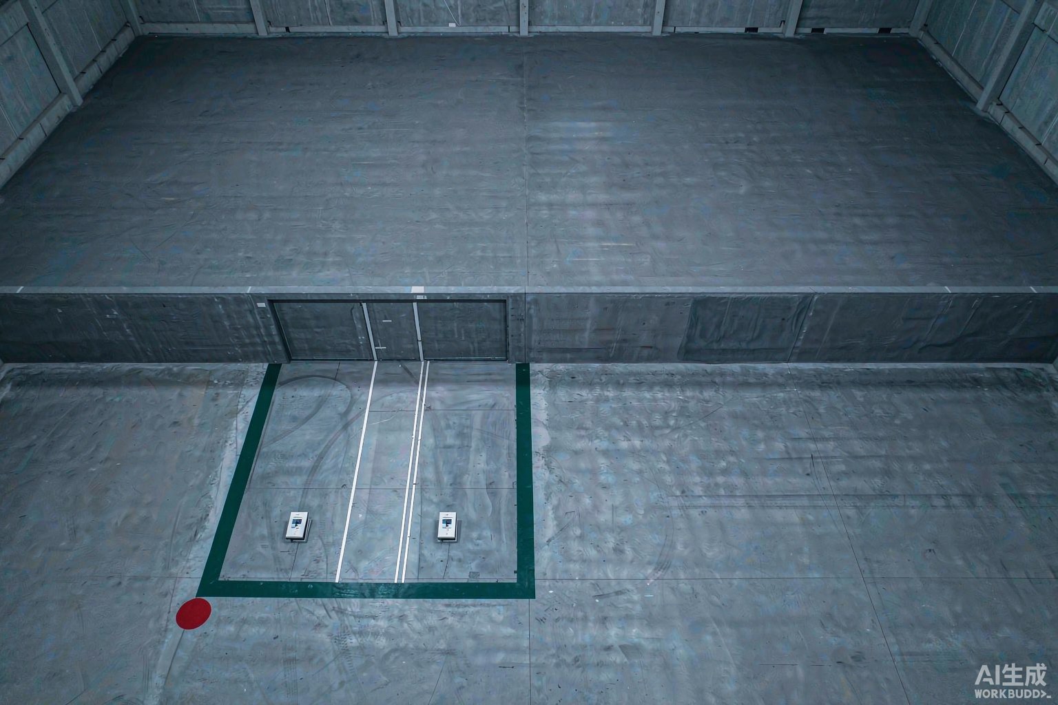
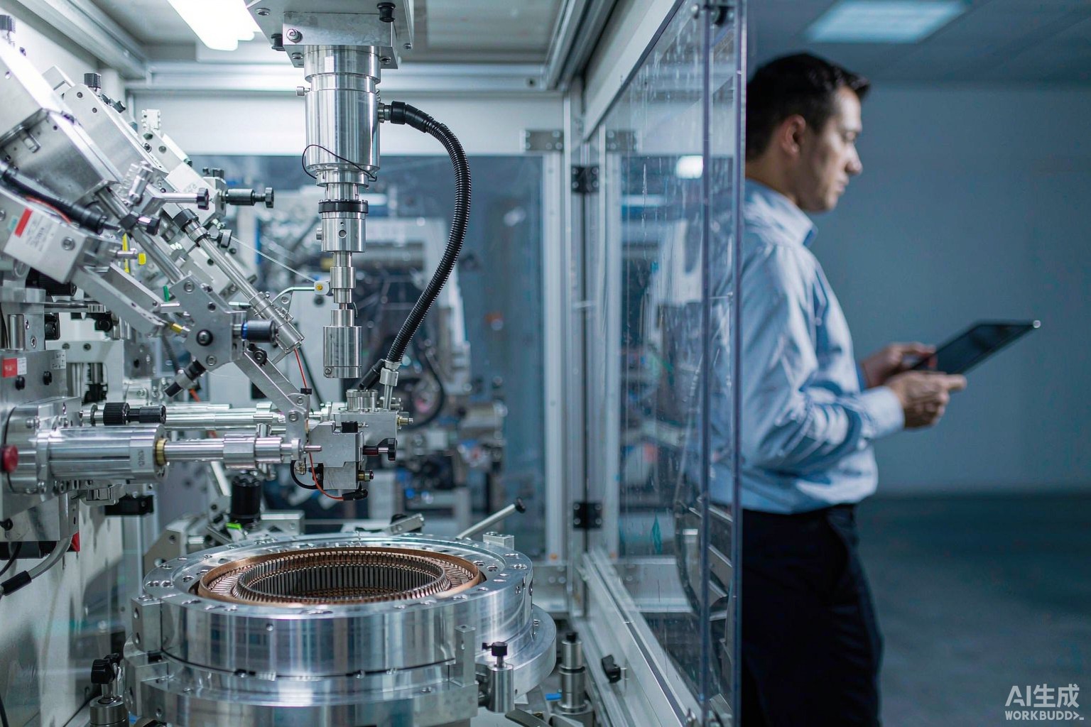
Fig. 1 - A layout drawing shows that footprint includes access, services and material flow. Illustrative image, AI-generated, not a product photograph.
Environment, floor and handling constraints
Ambient conditions set the operating envelope. State the acceptable temperature and humidity range, the cleanliness of the area, and any sensitivity to dust, vibration or drafts. A cell next to a press or a heat source can sit outside that envelope even when the rest of the factory is fine. Note any requirement for stable conditions, since a measurement or winding process that drifts with temperature needs the environment recorded as well as the machine.
| Site factor | What to specify | Who confirms it | Risk if missed |
|---|---|---|---|
| Installed footprint | Body, clearances, service envelope, flow | Layout or facilities engineer | Collisions and no working room |
| Electrical supply | Configuration, connection, isolation, earthing | Plant electrical engineer | Feeder or transformer needed late |
| Compressed air | Pressure, flow, dryness, filtration at use | Utilities or maintenance team | Unsteady air affects tensioners |
| Ambient envelope | Temperature, humidity, cleanliness, vibration | Process or quality engineer | Drift and unstable measurement |
| Floor and anchoring | Loading, levelness, isolation, fixings | Structural or facilities engineer | Costly floor work after order |
| Delivery and access | Door width, lift, route, disassembly needs | Logistics and installation team | Machine cannot reach position |
| Expansion allowance | Spare power, air, area for added stations | Production planning | Cell revised at first change |
Access for maintenance, loading and future expansion
Design the space around the tasks that happen after commissioning. Leave room to withdraw a spindle, replace a tensioner, open an electrical cabinet fully and remove a guard, and confirm that routine service does not require moving the machine or another cell. Check that wire spools, bobbins and finished parts can be loaded and removed without crossing the operator path. Tight access turns every simple service into a shutdown.
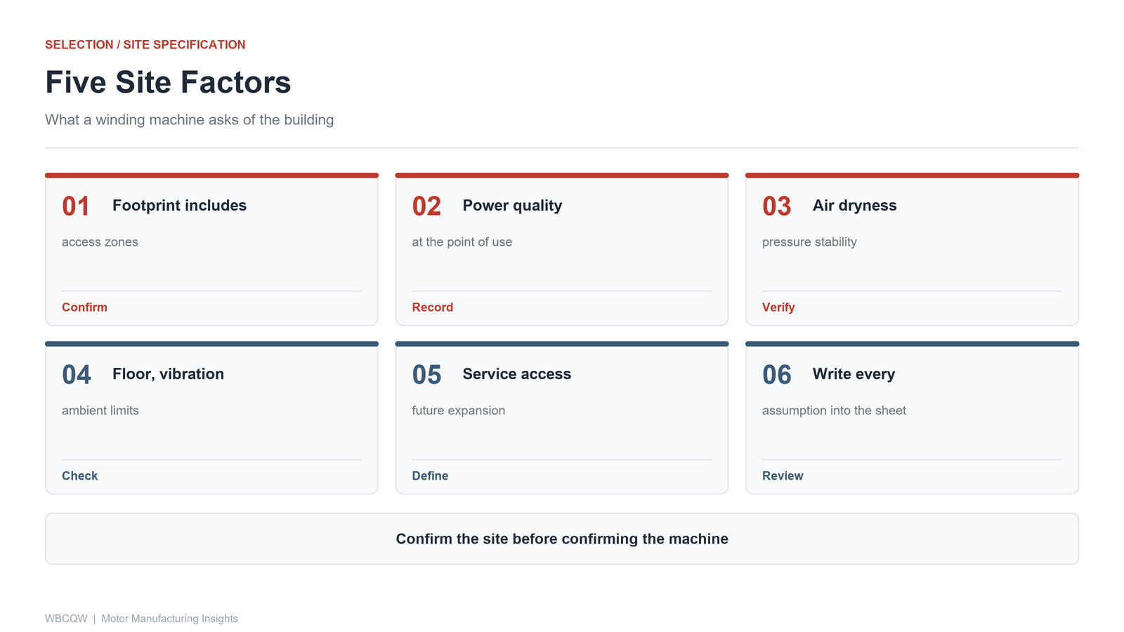
Fig. 2 - Five site factors that belong beside winding performance in a comparison. Illustrative diagram, not a product photograph.
A site-requirement comparison sheet
A comparison sheet turns these factors into something decidable. For each candidate machine, list the site factors with the value to be specified, the party who confirms it, and the risk if it is missed. Use identical rows for every machine so the columns line up, and mark each entry as confirmed against a drawing or measurement rather than assumed. The sheet belongs beside the performance comparison, not in a facilities file that nobody opens during selection.
The limits of this comparison are worth stating. A well-built sheet exposes the demands a machine places on a site and assigns responsibility for meeting them, but it cannot predict every installation issue or prove that a facility is ready. Actual conditions are confirmed by survey and measurement on the floor, and by commissioning tests after delivery. The sheet reduces late surprises and makes the assumptions visible; it does not replace the site survey or the acceptance test.