Choosing between one layer and several is usually presented as an electrical trade, yet most of the difficulty appears on the machine. Adding a layer brings a reversal, an interlayer surface, a lead that has to escape from inside the winding and a new set of faults that a turn count will never reveal. The comparisons below follow the part through traverse, insulation, termination and test, and ask what evidence should be requested before a route is signed off. For related background on insulation choices, see the discussion of comparing coil insulation approaches. The aim is a decision framework, not a specification of any rated voltage or turn count.
Why layer count is a process decision, not only an electrical one
Layer count sets the machine cycle as much as the inductance. A single-layer winding can often be produced with one continuous traverse and no climb, while a multi-layer part needs a controlled reversal, a defined crossover and usually a sheet or a changed pitch between layers. Each addition is a place where the process can drift, so the question is not only whether the design fits electrically but whether the line can hold the geometry at takt. The comparison describes tendencies rather than fixed rules, and a specific part geometry can invert them entirely.
Traverse control and layer reversal
In a single-layer coil the traverse has one job: place each turn beside the previous one at a pitch near the wire diameter and reverse once at the flange. In a multi-layer coil the same mechanism must also climb, hold a reversal dwell and shift the crossover so that layer two does not stack directly on layer one. Pitch expressed per spindle revolution, rather than as a feed rate, is what keeps the two behaviours comparable across speeds.
Reversal is where the two routes diverge most. A single late reversal shows as a pile-up at the flange; in a stacked winding it also decides where the next layer starts, so a small error repeats and grows. An interlayer sheet or a deliberate pitch change can stabilise the climb, but each is an extra item to verify. Where tension is used to force a clean reversal, the resulting enamel and breakage risk belongs in the planning of winding test coverage rather than being left to visual inspection alone.
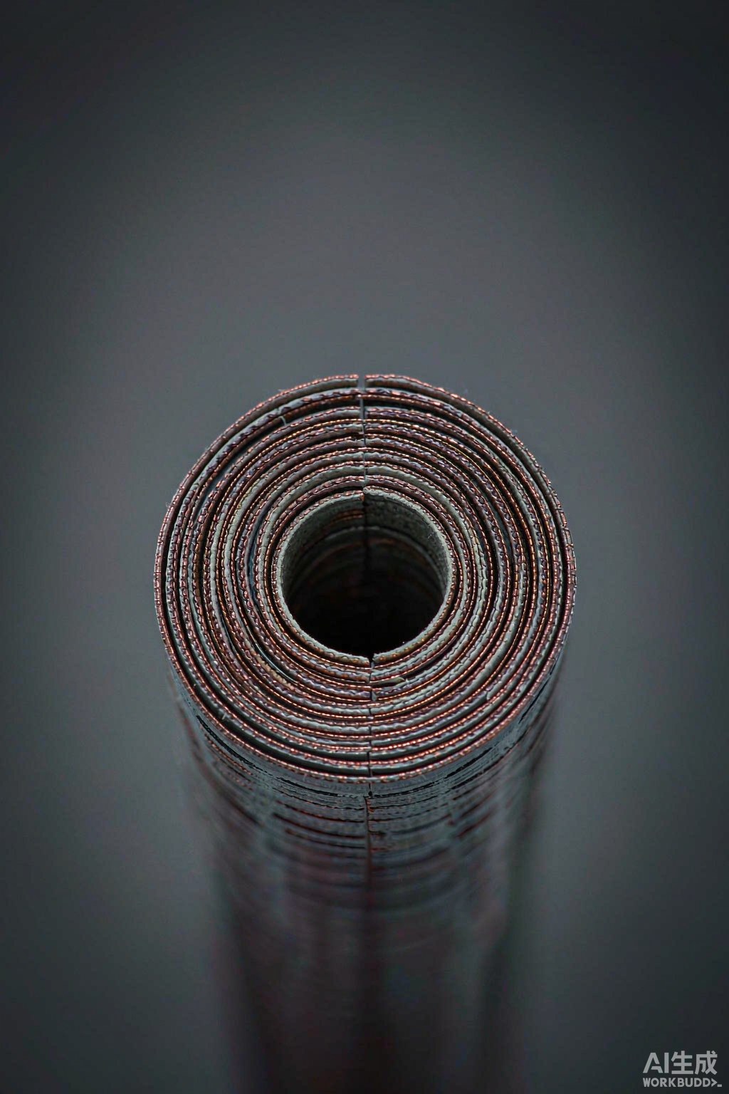
Fig. 1 - A cut section shows how layer count changes packing, insulation and lead routing. Illustrative image, AI-generated, not a product photograph.
Inter-layer insulation and creepage margins
A single-layer winding puts its main insulation concern at the bobbin and at the leads; adjacent turns sit at nearly the same potential. Once a second layer is added, the voltage between the first and last turns of neighbouring layers can be far larger than between adjacent turns, so the interlayer interface becomes the critical one. Margin paper, a sheet, or graded enamel build all exist to manage that stress, and the choice depends on how the winding is started and finished.
| Dimension | Single-layer coil | Multi-layer coil | Evidence to request |
|---|---|---|---|
| Traverse | One continuous pitch, single reversal | Pitch, dwell and shifting crossover | Recorded pitch and reversal log |
| Layer interface | Adjacent turns near equal potential | Voltage between stacked layers | Insulation method and creepage path |
| Insulation | Bobbin and lead focused | Interlayer sheet or margin build | Section or placement record |
| Termination | Both leads at the flange | Inner lead needs an exit path | Lead routing and end-turn drawing |
| End-turn fit | Shape set by flange | Buried crossover can add bulk | Dimensional check including ends |
| Characteristic fault | Gap or flange pile-up | Layer-to-layer or crossover fault | Chosen test per failure mode |
| Test emphasis | Resistance and leakage | Surge or hipot between layers | Test coverage by route |
Termination, lead exit and end-turn shape
Termination is often where a multi-layer part earns its complexity. A lead starting on an inner layer has to be brought out without crossing the turns above it, which means a planned exit path, a sleeve or a formed end-turn, and a fixture that holds the lead during the rest of the wind. A single-layer coil usually exposes both ends at the flange, so termination is simpler but the end-turn shape is still constrained by the assembly envelope.
Which tests detect which failure mode
Different faults need different tests, and a pass on one does not excuse skipping the others. Turn count and DC resistance catch gross placement and length errors in both routes. A layer-to-layer insulation fault in a multi-layer coil is more likely to appear under a hipot or surge comparison than under a resistance check, while a single-layer scuff against the bobbin may only show as a leakage or hipot failure. Inductance and a layer appearance check sit alongside these, not in place of them.
Test selection should follow the failure modes the chosen route actually creates. A single-layer line has little reason to invest in layer-to-layer surge screening, and a multi-layer line that skips it assumes a risk it has not measured. Limits belong here too: electrical tests are sampled and indirect, they can miss an intermittent fault that appears only at temperature or after vibration, and a clean test result never proves that the interlayer sheet was placed correctly on every part.
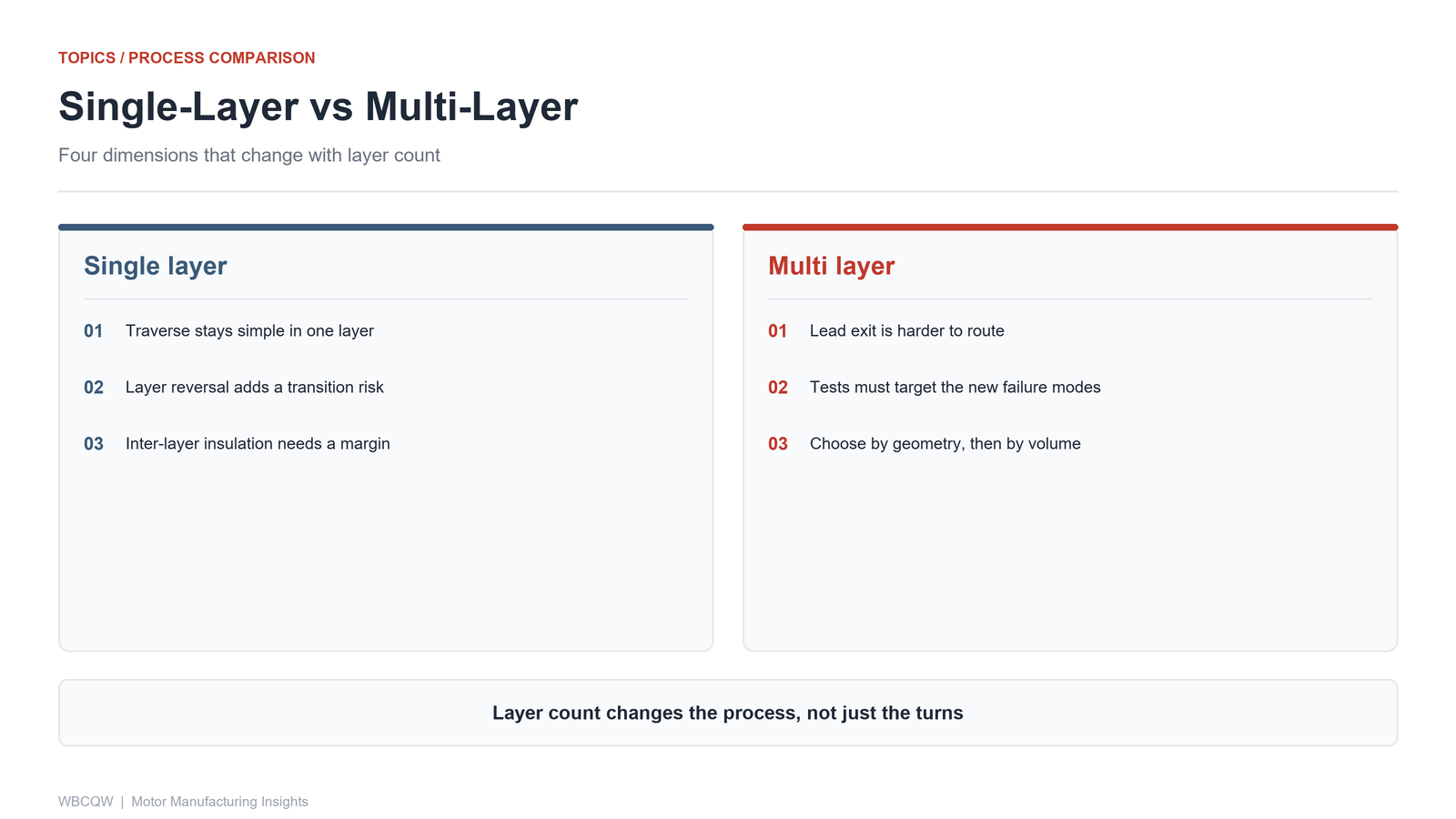
Fig. 2 - Four dimensions where single-layer and multi-layer windings diverge. Illustrative diagram, not a product photograph.
Choosing a route by part geometry and volume
A short decision record helps: state the geometry constraint, the insulation path, the termination method and the test that will catch the dominant fault, then note which assumption is least proven. That last line is the useful one. Whatever route is chosen, the comparison holds only for a defined part and wire lot; a change in bobbin flange radius, enamel build or lead hardware can move the balance, so the decision is worth revisiting when any of those change.