Blaming the wire is the fastest way to close an insulation complaint and the least likely to keep it closed. Enamel film is thin and the wire travels through a chain of guides, eyes and tensioner surfaces before it ever reaches the part, so a fault that appears near the guide usually originates somewhere along that path rather than in the spool. The checklist below works backward from the symptom to the contact that caused it, and ends with an ordered sequence that avoids changing three things at once. For a related view of mechanical causes, see the root-cause checklist for wire breakage. The focus here is diagnosis, not a claim about any specific wire grade or voltage rating.
When insulation damage is a path problem, not a wire problem
A wire lot is a convenient suspect because it is easy to replace, but a replaced spool that produces the same scuff proves the cause was elsewhere. Enamel is removed by abrasion, by a sharp edge, or by a contact loaded beyond what the film can bear, and all three are properties of the path. Groove wear, a chipped ceramic eye, a burr on a tensioner cap and a guide with too small a radius each leave a characteristic mark on the wire.
First confirm the symptom and where it appears
Before touching a setting, establish exactly what the damage is and where along the wire it sits. Is the enamel scraped on one side only, softened, or cracked in a repeating pattern? Collect a short length that includes the damaged region and the intact wire on both sides, and mark which direction faced the guide. A one-sided scuff points to a contact; an all-around brittleness points toward heat or material.
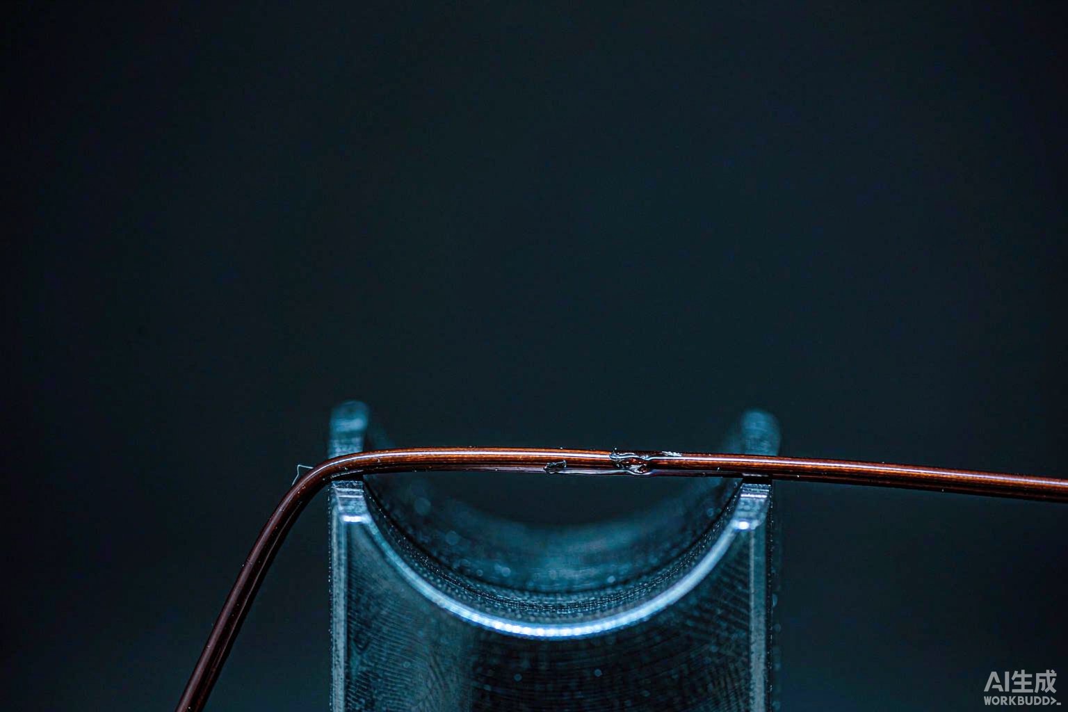
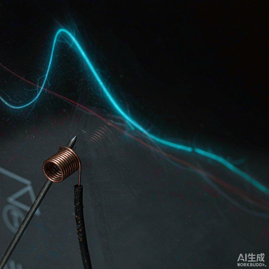
Fig. 1 - A scuffed guide surface is a common place to start an insulation-damage investigation. Illustrative image, AI-generated, not a product photograph.
Guide grooves, radii and surface finish
A guide that has run the same wire for a long time develops a groove, and that groove becomes the sharpest edge in the path. Inspect every eye, roller and nozzle under bright grazing light and run a clean filament or a fingernail test across the contact to feel a nick that the eye misses. The bend radius is equally important: a wire forced around too tight a corner stretches the film on the outside of the bend and can crack it without any visible cut.
| Symptom | Likely cause | First check | Record to keep |
|---|---|---|---|
| One-sided scuff | Worn or sharp guide contact | Inspect grooves under grazing light | Sample with mark orientation |
| Cracked film on outer bend | Guide radius too small | Check bend path and eye size | Wire path sketch and guide IDs |
| Damage at start-up only | Tension peak on acceleration | Capture tension trace at ramp | Trace and program speed |
| Single-event scrape | Spool over-run and snap | Observe payout on deceleration | Spool and brake condition |
| Scuff at discrete points | Handling or splice damage | Inspect lead and fixture contacts | Operation where it appears |
| All-around brittleness | Heat or material condition | Review cure and ambient state | Wire lot and exposure record |
| Recurring at one position | Persistent unloaded contact | Recheck guide alignment | Guide angle and replacement log |
Tension peaks, acceleration and spool behaviour
Steady tension is rarely the value that breaks a film. Start-up, deceleration, traverse reversal and a spool that over-runs all produce peaks far above the setpoint, and a peak can press the wire into a guide hard enough to scrape the enamel in a single event. If the machine records a tension trace, compare the moment of damage with the trace; if it does not, a hand-held check at the same point in the path is the honest substitute.
Handling, splices and downstream contacts
Not every insulation fault happens before the coil. A splice, a lead that is bent back sharply, a degreasing step, or a contact with the fixture after winding can all remove enamel and then be mistaken for a guide problem. Trace the wire beyond the nozzle as well as before it, including any pinch point at the cut and the surface the finished lead rests against. Handling damage usually appears at discrete points rather than along a continuous length.
The distinction has a practical consequence for the record. A guide fault repeats at a fixed position in the cycle, while a handling fault clusters around a specific operation or operator. Where downstream contacts are suspected, the guidance on handling and splicing fine wire applies without changing any machine parameter. The limit is that visual inspection of enamel is insensitive to a thin, healed-over scuff, so a suspect part should be confirmed electrically rather than cleared by appearance alone.
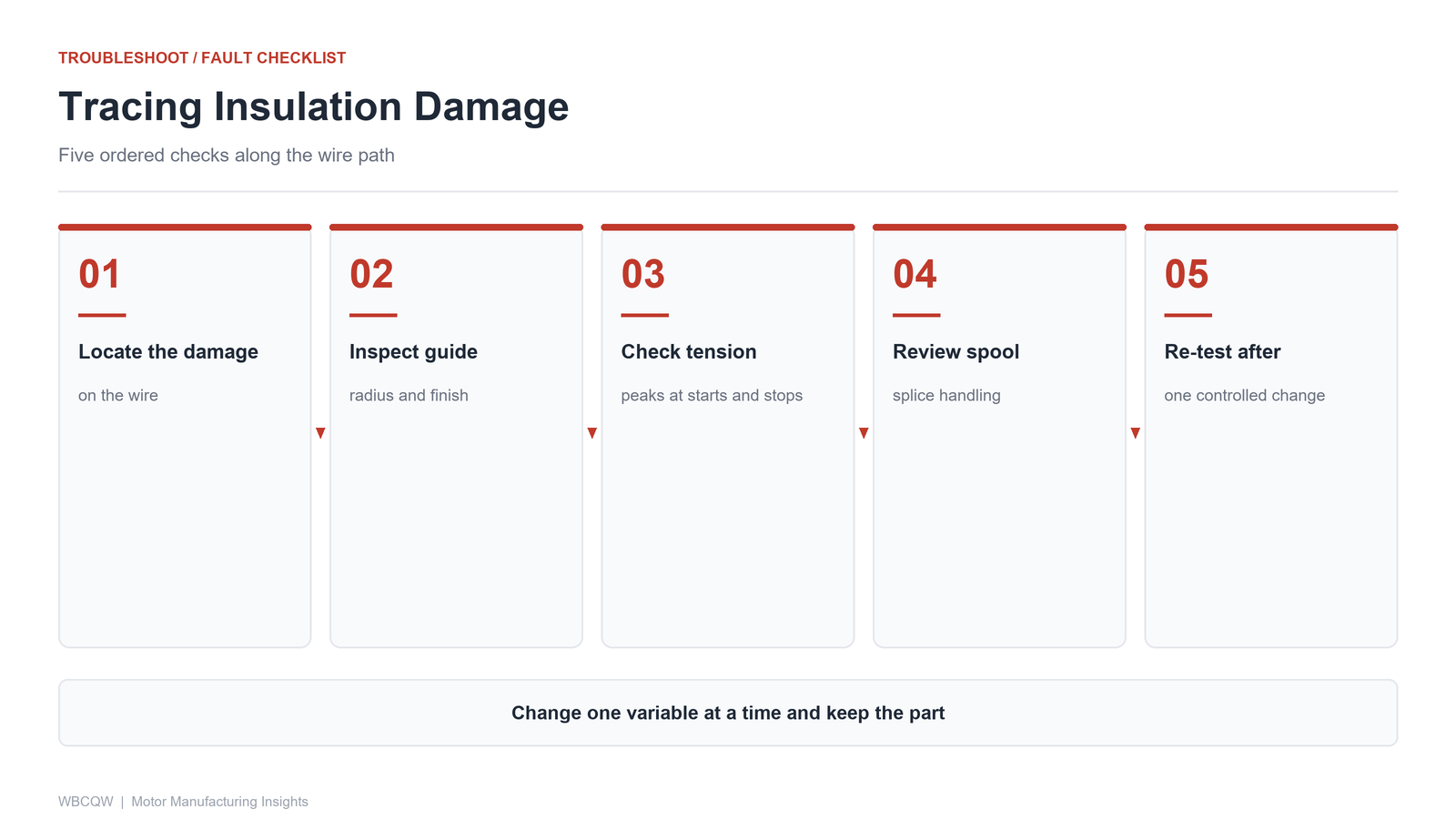
Fig. 2 - Five ordered checks for tracing insulation damage back through the wire path. Illustrative diagram, not a product photograph.
A five-step investigation sequence
Order the work so that each result narrows the next step. Confirm and locate the symptom on a labelled sample; inspect guide grooves, radii and finish; check tension peaks and spool behaviour at production speed; trace handling, splices and downstream contacts; then change one variable and re-run with a retained sample. Keeping this order prevents the common mistake of replacing the spool and a guide together, which leaves no way to tell which change helped. Keep the retained sample until a single cause is confirmed, not merely until the line restarts.
Write the sequence onto the fault sheet with a line for the result of each step, and stop when a single cause explains the mark. Such a sheet has limits: it organises an investigation, it does not measure insulation strength, and it cannot detect an intermittent fault that appears only under a different wire lot or ambient condition. Used consistently, though, it turns a recurring complaint into a reproducible finding instead of a standing argument about the wire.