A setpoint on a tensioner screen is a request, not a measurement. Between that number and the force actually delivered to the wire sit guide friction, wrap angles, a device that can drift, and a spool whose behaviour changes as it empties. Verifying tension means measuring the delivered force at the point where the wire meets the part and showing that it sits inside the band the process was qualified for. The procedure below covers preparation, one repeatable measurement, comparison and the record that makes the next check comparable. For the surrounding setup routine, see the note on setting up a tension measurement routine. It deliberately avoids quoting any target force, since that belongs to the specific part and wire.
What a tension verification is meant to prove
Verification answers a narrow question: on this machine, with this path and this wire, is the force at the point of use the same as the value the setup sheet assumes? It is not a calibration of the tensioner in the metrological sense, and it does not certify the instrument. It simply closes the gap between a setpoint and reality before a batch is committed, so that a later drift can be recognised as drift rather than as a mystery.
Prepare the wire path, instrument and part
Thread the wire exactly as production will run it, through the same guides, the same number of wrap angles and the same tensioner, because friction and geometry are part of the delivered force. Confirm the instrument is within its own valid period and zero it with no wire loaded, then check that a representative part or a dummy of the same flange geometry is mounted. A path rigged differently for the check will produce a clean number that describes the wrong setup.
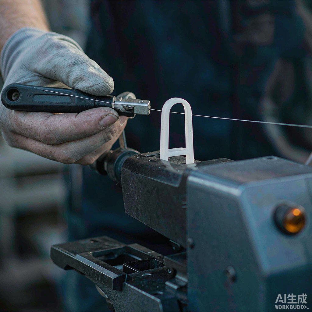
Fig. 1 - A hand-held tension check at the guide gives a value that matches the real wire path. Illustrative image, AI-generated, not a product photograph.
Measure at the point of use, not at the spool
Place the gauge as close as the geometry allows to where the wire enters the nozzle or the part, with the same free length and wrap the production path uses. A reading taken near the spool ignores every guide and every friction loss downstream, so it can look correct while the coil is wound too loose or too tight. Take several readings across a full cycle, including a reversal, and note the peak as well as the steady value.
| Step | Input to set | What to record | Pass condition |
|---|---|---|---|
| Thread production path | Guides, wraps, tensioner, mounted part | Wire lot, program revision | Matches qualified setup |
| Stabilise and zero | Normal running state, zeroed gauge | Instrument ID and valid period | Stable line, zero confirmed |
| Measure at point of use | Gauge at nozzle, full cycle | Steady value and peak | Readings captured at reversal |
| Compare with window | Qualified band, production speed | Pass or adjust decision | Both values inside the band |
| Record baseline | Point, conditions, speed, date | Full baseline sheet | Reproducible by another person |
| Set re-check trigger | Spool, guide, program, defect events | Trigger rule and interval | Trigger written on the sheet |
Compare readings with the process window
Compare the measured steady value and peak against the window recorded on the qualified setup sheet, not against a value that seems reasonable. The window should already state an allowable band and the conditions it was set under; if it does not, the comparison is an opinion rather than a test. Where a reading falls outside the band, adjust one element, usually the tensioner setpoint or a guide, and repeat the full measurement rather than nudging until the display looks better.
Treat a borderline result conservatively. A value sitting at the edge of the window at low speed can move outside it during acceleration, so verify at the intended production rate before accepting. This is also where a second opinion helps: the guidance on structuring a winding defect log is useful if out-of-window tension has been producing named faults, because a log ties the force to the symptom it caused. A pass at one speed still does not prove the window holds at takt.
Record the baseline and set a re-check trigger
Write the accepted readings into a baseline that another person could reproduce: instrument used and its valid period, point in the path, wire lot, program revision, speed, steady value and peak, ambient conditions, and the date. Store it beside the retained first article or setup sheet. A baseline that omits the point of measurement cannot be compared with a later check, because the same force at a different location is a different result.
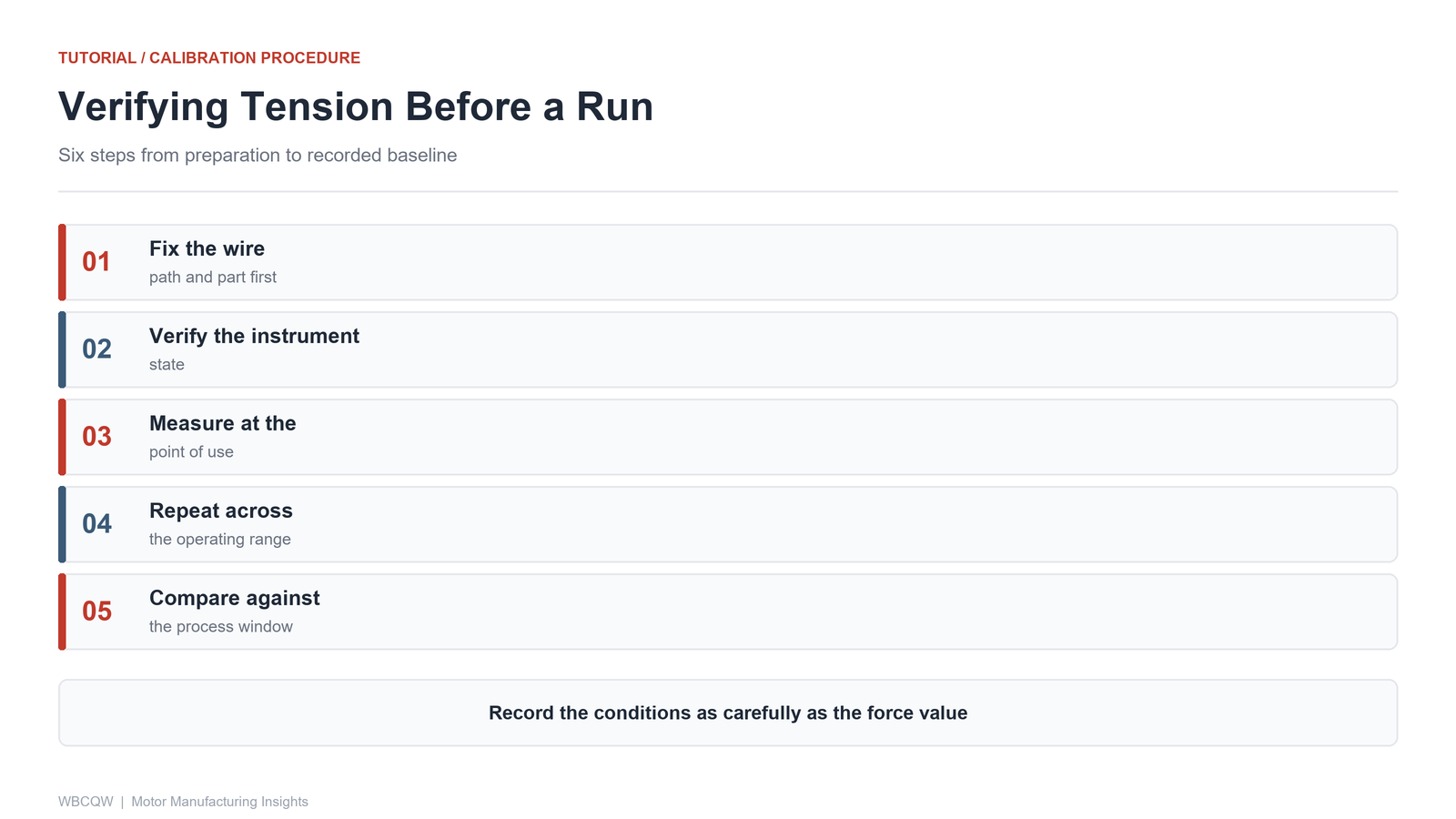
Fig. 2 - Six steps to verify tension and record a comparable baseline. Illustrative diagram, not a product photograph.
A short step-by-step procedure
Reduce the whole routine to a card at the station. Thread the production path and let the line stabilise; zero and confirm the instrument; measure steady value and peak at the point of use; compare both with the qualified window at production speed; record the baseline; and attach a re-check trigger. Six steps, each with one input and one line on the sheet, are easier to follow under time pressure than a paragraph of explanation. Post the card beside the setup sheet, so the force reading and its baseline are always reviewed together at the station.
Close the card with its own limits. The procedure verifies a delivered force under one set of conditions, it does not measure tension continuously, and it cannot detect a fault that appears between checks or under a different wire lot. A clean verification is evidence that the setup was comparable to its baseline on that day, nothing more. Repeated checks and a controlled baseline are what turn that single result into confidence, which is the modest but real aim of the whole exercise.