Wrong traverse pitch rarely begins in the program. It is produced by a motion chain - drive, motor, encoder and transmission - and a drifting layer is usually a ratio that moved, not a setpoint that needs editing. This article follows that chain in order and keeps a separate review of machine support and upgrade policy out of scope. The aim is a repeatable inspection path rather than a tuning recipe.
Why pitch is a motion-chain property
Traverse pitch is the advance of the wire guide per spindle revolution, so it is a ratio between two motions, not one number in a controller. A program requests a pitch; the delivered pitch is whatever the traverse axis does while the spindle turns. Any error in either motion or their coupling appears as a placement fault - a wide turn, a ridge, a creeping reversal.
This changes what you measure. Confirm the result at the wire, not on the display, because that is where the part is made. It also explains why two machines on one program place turns differently, and why one machine drifts after a mechanical change. The program is an instruction; the chain is the plant that carries it out.
Drive, motor and transmission in the traverse axis
The traverse axis starts with a drive closing a loop around a motor, then a stage converting rotation into linear guide motion. Each link adds behaviour: the drive sets correction gain, the motor sets how smoothly small corrections are followed, and a screw or belt sets how faithfully rotation becomes translation. A loose transmission leaves the controller chasing a position it cannot see.
Configuration matters as much as hardware. Gear ratios, lead, electronic gearing and commanded pitch must agree; a mismatch produces a systematic offset that looks like a process fault. Confirm the axis is genuinely under position control and that spindle-to-traverse scaling is documented. A guide to comparing what a specification includes helps when the paperwork is vague.
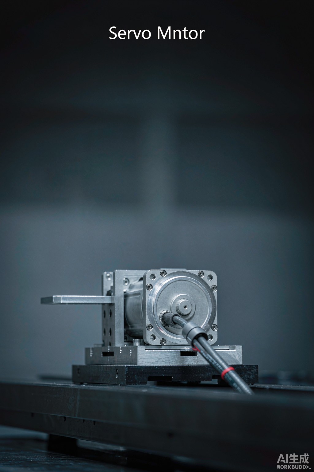
Fig. 1 - The encoder and drive form the feedback loop behind repeatable traverse pitch. Illustrative image, AI-generated, not a product photograph.
Encoder resolution, referencing and lost position
The encoder turns the loop from a guess into a measured correction. Resolution sets how finely position is reported, but a fine encoder on a compliant stage still reports the wrong place precisely. What matters is that reported traverse position stays consistent with spindle position across the layer. A lost or shifted reference produces an offset that repeats from part to part.
Incremental systems must re-find a reference after power loss or homing, and that method belongs in the record. Absolute systems avoid the step but still depend on setup and a calibrated transmission. A uniformly shifted coil points to referencing; irregular spacing points to following or resolution. Separating the two patterns saves misdirected adjustment.
| Component | What it controls | Drift symptom | First check |
|---|---|---|---|
| Servo drive | Loop response and correction gain | Following error at speed changes | Commanded versus reported position |
| Traverse motor | Smooth small-motion response | Jerky or rounded reversals | Motor current and following trace |
| Rotary encoder | Reported axis position | Uniform offset after homing | Reference and index signal |
| Transmission screw or belt | Rotation to linear conversion | Gradual error along the layer | Backlash and coupling tightness |
| Linear guide and carriage | Straightness of guide motion | Placement error at one end | Slide friction and alignment |
| Spindle feedback | Turn counting and ratio basis | Whole-layer spacing change | Spindle encoder and gearing |
| Controller scaling | Program pitch to axis units | Systematic offset on every part | Electronic gearing and lead setting |
Backlash, compliance and mechanical play
No feedback loop reports what happens downstream of the encoder. Backlash, a loose coupling, belt stretch and carriage compliance all add motion the motor sees but the guide does not. These effects are direction-dependent, so they surface at a traverse reversal where a layer transition is most sensitive. Lost motion at each reversal shifts the next layer's start point.
Compliance is elastic rather than a fixed gap: the stage deflects under load and springs back, so the error scales with acceleration and tension. Both are mechanical, and neither is fixed by a controller parameter. Inspect coupling tightness, belt condition, guide preload and free play alongside the electronic diagnostics. A machine that cannot hold position mechanically keeps repeating the fault.
What compensation can and cannot correct
Drives offer real tools - backlash compensation, pitch-error mapping, following-error limits, feed-forward - that reduce a repeatable, measurable error. The key word is repeatable: the same error at the same position in the same direction can be learned and cancelled. Random play, thermal drift, a slipping coupling or a speed-dependent fault cannot. A correction applied to noise hides one run and returns as a new fault.
There is a hard boundary at the wire. Compensation lives inside the loop, but pitch is correct only if the delivered motion gives the intended placement on the real part. Enamel thickness, tension and guide deflection sit outside it. This is the honest limit: software can cancel a known axis error, but it cannot certify the coil. Placement must be confirmed on a wound part.
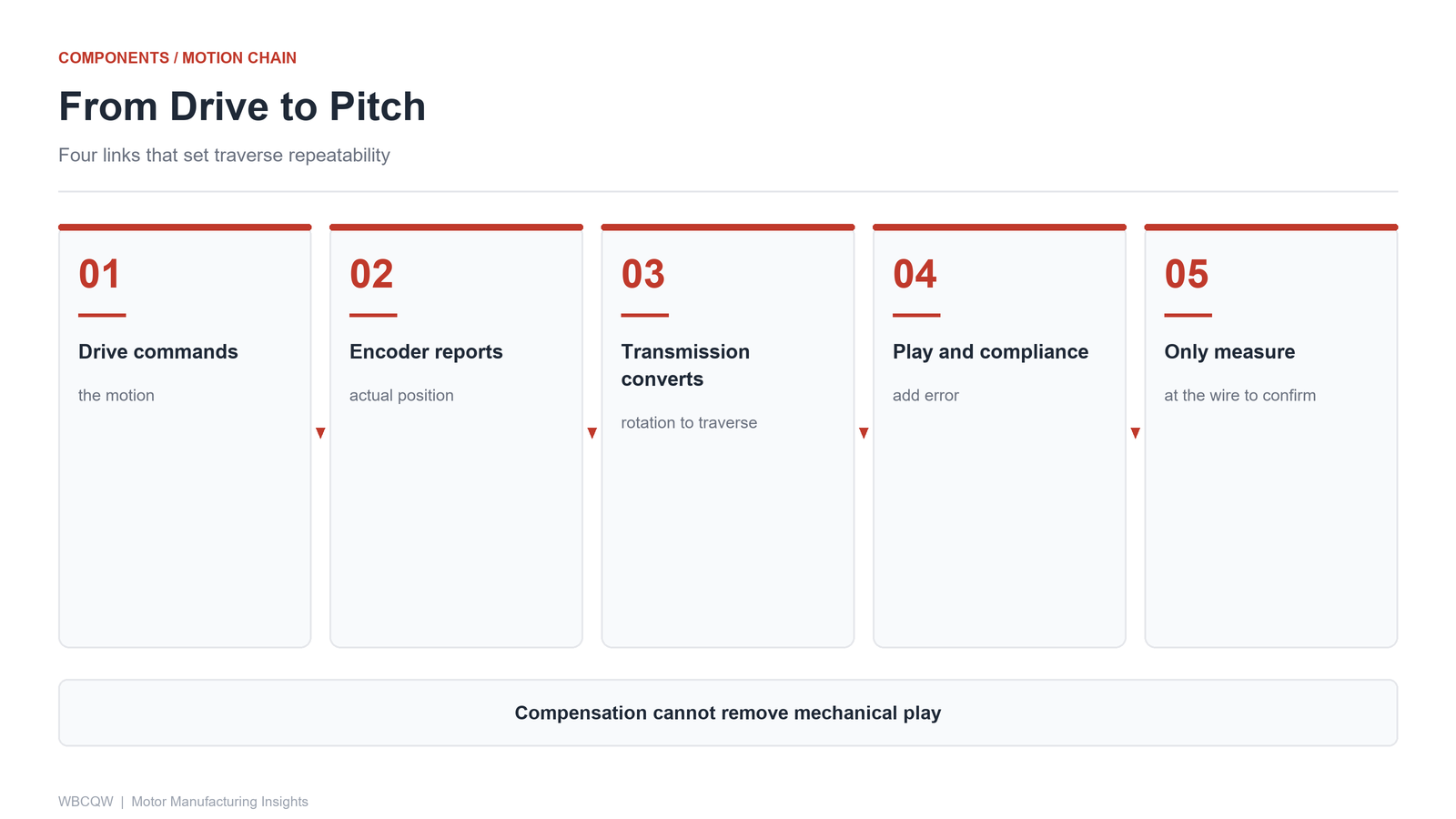
Fig. 2 - Four links in the motion chain that determine winding pitch. Illustrative diagram, not a product photograph.
A motion-component inspection list
Work from the wire back toward the program so the evidence stays physical. Record commanded and measured pitch, spindle and encoder setup, referencing method, transmission condition and active compensation. Note the error's direction, where along the layer it appears, and whether it repeats. Those three observations localise the failing link better than any single reading.
Keep the list short and comparable across shifts; change one thing at a time, retain each part, and record conditions as well as outcomes. Its limit is plain: it finds a fault already present and repeatable, not a coupling about to loosen or a bearing beginning to wear. That drift needs trend data and scheduled mechanical checks, which are maintenance, not diagnostics. Used honestly, it turns a vague complaint into one traceable question.