A robotic joint leaves little spare volume, and the coil inside it is judged by more than turn count. It sits close to bearings, sensors and a housing that must close cleanly, so end-turn shape, lead routing and insulation margins become assembly issues. Reusing a stator platform is tempting but rarely clean. These notes set out the handling and tolerance questions that make the part distinct, with a review of how motor stator uniformity is specified kept aside.
Why an actuator coil is not a small stator
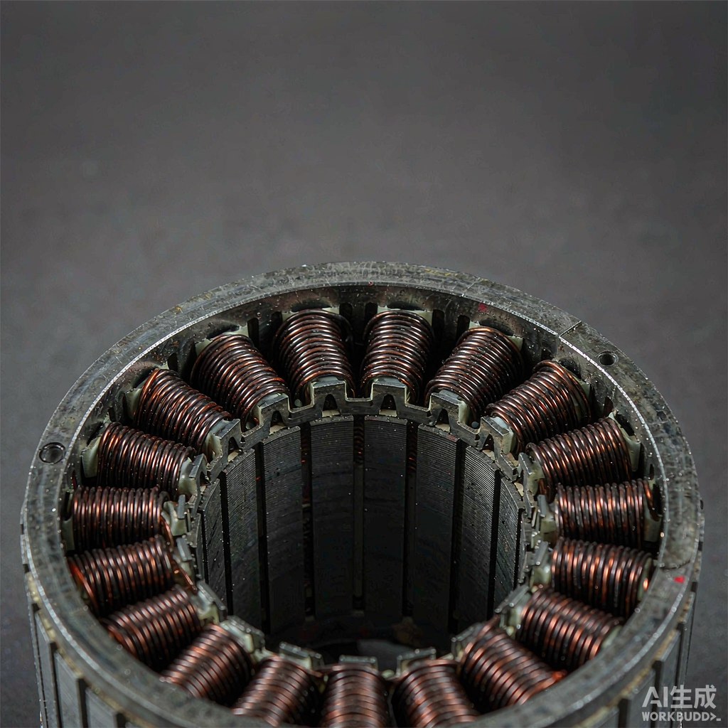
A stator is wound into a laminated core whose slots define the winding space. An actuator coil often has no such core, or shares a compact housing with a gearbox, a brake and position sensing. The winding is constrained by an assembly, not a slot, and a dimension harmless on a stator - a tall end turn, a stiff lead - can stop the housing closing.
Thermal sensitivity adds a second difference. A joint dissipates heat into a small enclosed mass, so how the winding packs and contacts the housing matters as much as its electrical value. A platform built for a ventilated stator does not respect those constraints, and the first sign of a poor transfer is usually a fit or temperature problem at assembly.
Compact geometry and the winding window
The winding window is the usable space between the flanges, bobbin walls or core features that bound the coil. In a joint it is short and often narrow, so build height limits how many layers fit and how the traverse must reverse. A program written for a wider window tries to place turns where there is no room, producing a bulge that fouls the housing.
The reversal at a narrow window's edge is a specific risk. There is little clearance for the wire to climb to the next layer, so the crossover and any interlayer material must be planned into the geometry rather than left to defaults. This is where a stator recipe, with generous slots, fails most quietly.
Fine wire handling and insulation margins
Compact coils often use fine wire to fit the required turns into a small window, and fine wire narrows the margin between a stable setpoint and a damaged turn. Guide radii, surface finish and tension peaks matter more than on a heavier stator winding. Where the coil sits close to a metal housing, creepage and clearance are assembly dimensions, and scuffed enamel is a reliability problem.
Specify wire from the actual spool - bare diameter and enamel grade - and treat margins as reserved space in the window. How bobbin features constrain a winding program is useful here, though the housing is tighter than a free bobbin. The limit is plain: gentle handling reduces damage but cannot enlarge a window the assembly has already fixed.
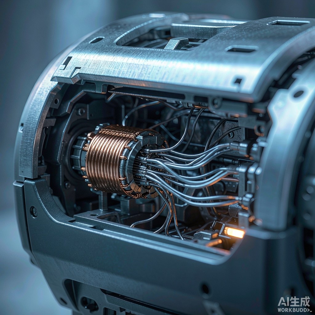
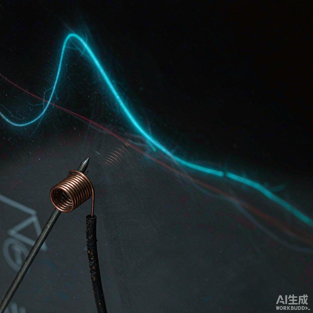
Fig. 1 - Compact actuator assemblies leave little room for end turns or lead routing. Illustrative image, AI-generated, not a product photograph.
Termination, lead routing and assembly clearance
On a stator a lead usually has somewhere to go. In a joint the leads must route through a crowded housing, past gears and sensors, to a termination that may move as the joint rotates. Lead length, stiffness, sleeving and bend radius become winding decisions with assembly consequences. A lead too long fouls a moving part; one dressed too tightly stresses the enamel at the exit.
Termination method also interacts with the tolerance stack. Soldered, crimped or welded ends occupy different space and tolerate different strain, and the choice must suit the joint's thermal and vibration environment. Treat the exit region as part of the coil specification, because a coil that winds perfectly but cannot be terminated in the housing is a failed part.
| Application | Coil geometry | Critical tolerance | Typical check |
|---|---|---|---|
| Robotic joint actuator | Compact, short winding window | Finished coil envelope and height | Fit against closed housing |
| Motor stator | Slotted laminated core | Slot fill and phase balance | Resistance and placement across slots |
| Small transformer | Flanged bobbin, layered | Creepage margin at flange | Margin and layer build inspection |
| Actuator lead exit | Fine leads in tight space | Lead routing and insulation | Clearance and rub check at assembly |
| Sensor-adjacent coil | Coil near position sensing | End-turn profile and stray field | Envelope and functional check |
| High-volume stator | Generous slot geometry | Turn matching per phase | Comparative phase measurement |
| Compact fine-wire coil | Many turns, fine wire | Enamel integrity and tension | Visual and continuity inspection |
Where the tolerance stack differs from motor coils
A stator accumulates tolerance mostly within its own lamination, slot and end-turn geometry; the coil is measured against the core it sits in. An actuator coil accumulates tolerance against several neighbours at once - housing, bearings, gearbox and sensing - so a dimension fine in isolation can fail in the stack. The winding supplier controls only part of that chain, which is why coil-level inspection cannot certify the joint.
This is the clearest place a stator platform does not transfer. Its checks target slot fill and phase balance; the actuator needs envelope, lead clearance and interface dimensions. The limit is explicit: winding can deliver a coil to a defined envelope, but the fit of the assembled actuator is a system property the assembly owner must verify.
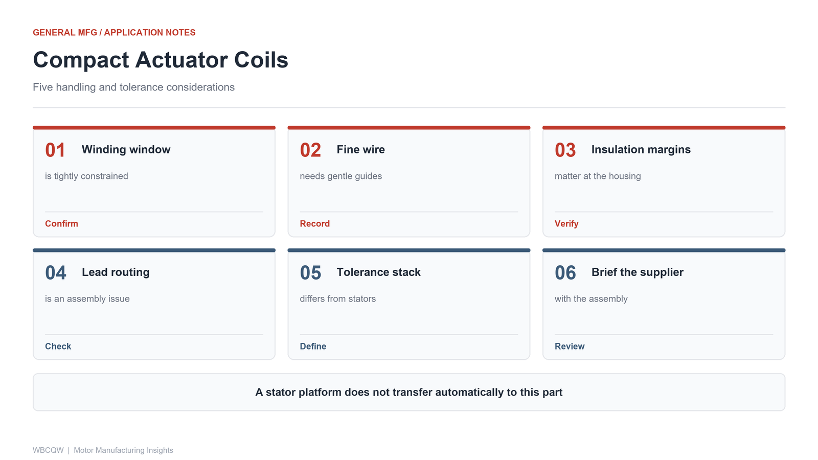
Fig. 2 - Five handling and tolerance notes for compact actuator coils. Illustrative diagram, not a product photograph.
A supplier briefing note for a non-motor part
A useful briefing gives the supplier the assembly, not just the coil. Include the housing drawing with closed-envelope dimensions, the winding window and reserved margins, the wire specification from the real spool, lead exit and termination requirements, and the inspection points the assembly will check. State which dimensions are fixed by the assembly and which the winding may vary, and ask for a first article fitted into a housing.
Keep the note short and testable, and attach a retained sample so the agreed envelope has a physical reference. Its honest boundary: a briefing reduces ambiguity but cannot remove it, because until a coil is assembled into a real joint the fit is a prediction. The first assembled article, inspected against the housing, turns that prediction into evidence.