In a small transformer the bobbin is not a passive carrier; it is the drawing the winding program must obey. Flanges, the winding window, insulation margins and lead slots set hard boundaries on where wire may go. A program written for a different core often winds a coil that looks correct yet fails on fit, creepage or termination. Read those features from the physical part before entering any parameter. Choosing equipment that respects them is separate, covered in our guide to selecting a transformer winding machine.
Why the bobbin sets the winding envelope
Every turn must fit inside a volume defined by the bobbin: the width between flanges, the depth the core window allows, and the height the walls permit before wire climbs over. The program controls where the nozzle goes, but the bobbin decides where it is allowed to go; no tuning makes an oversized coil fit.
Because tooling fixes the envelope, a change of bobbin supplier or a new mould can invalidate a proven program even when the part number is unchanged. Treat the bobbin as a measured input, not an assumed constant. This addresses geometry, not the dielectric design that decides how much margin a product needs.
Flange height and usable winding width
Usable winding width is the clear distance between the inner flange faces, less any margin at each end. Flange height sets the maximum build before winding rises above the wall. A tall flange gives more build room but narrows nozzle access; a low flange does the opposite. Read the two together.
The program should use a slightly reduced effective width, so the first and last turns of every layer stay clear of the wall. Recording the measured clear width and flange height makes the program self-describing. A catalogue width is nominal; what matters is measured from the actual parts.
Creepage margins and insulation coordination
Margins are the unwound bands left at one or both ends of a winding to keep conductors a defined distance apart. A margin reduces the usable width and changes the turns-per-layer and layer count. If a program fills the full clear width, primary and secondary can end up closer than the product allows.
Insulation coordination is a product-level decision, so the process should treat the required margin as an input it must not reinterpret. Tape adds thickness that must be counted in the build. The honest limit is that a machine can hold a margin geometrically but cannot verify the finished assembly meets a dielectric requirement; that belongs to the electrical test.
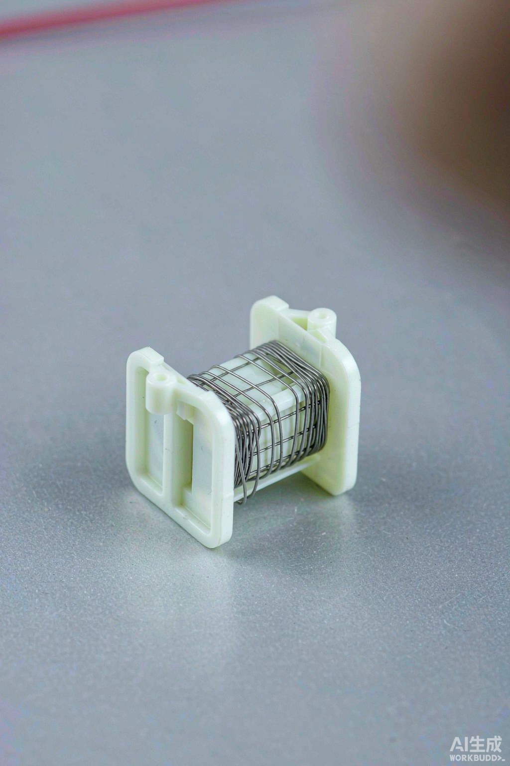
Fig. 1 - A blank bobbin shows how flange height and margins define the usable winding area. Illustrative image, AI-generated, not a product photograph.
Layer build-up and traverse reversal at the flange
Each layer raises the winding surface, so the traverse correct for layer one is slightly wrong for layer two. As build grows the effective width shrinks, so the reversal point must move inward or the top turns ride up the wall. A fixed reversal for every layer produces a coil flat at the bottom and bulged at the top.
Managing this means defining the reversal as a function of layer number, with a small inward step at each climb, plus a reversal dwell that lets the wire settle. These are comparative controls against a limit sample: they keep the profile consistent but cannot confirm the winding still fits the assembled core.
| Component | Winding constraint | Test or check | Why it matters |
|---|---|---|---|
| Flange height | Maximum build before wire climbs the wall | Measured wall height and build | Sets the safe layer count |
| Clear winding width | Effective width after margins | Measured distance between flanges | Fixes turns per layer |
| End margins | Reserved band at each flange | Margin width on the setup sheet | Keeps conductor separation |
| Interlayer tape | Added thickness at each layer | Tape counted in the build | Prevents an underestimated profile |
| Reversal point | Inward step as build grows | Profile against a limit sample | Avoids a ridge at the flange |
| Flange slot | Lead routing and exit position | Lead exit and sleeving check | Protects the lead and the wall |
| Core window | Total assembled build | Assembly fit check | Confirms the coil fits the core |
Lead exit, sleeving and assembly constraints
Leads leave through a slot, notch or over the flange, and that exit is a common place a program meets a physical limit. A lead pulled too sharply against a flange edge can damage the enamel. Sleeving adds thickness at the exit, so its space must be allowed for in the build, not discovered at assembly.
Start and finish leads should be defined as positions in the program, with a fixed length, strip and exit path applied in the same order on every part. The limitation is that a program controls lead placement, not the strain relief of the assembled transformer; a crowded exit usually needs a bobbin or layout change.
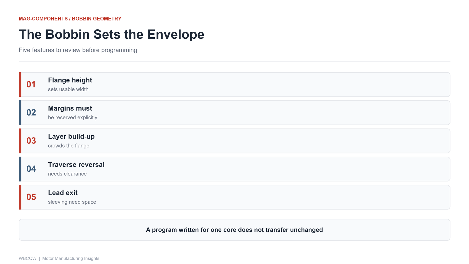
Fig. 2 - Five bobbin features that constrain a transformer winding program. Illustrative diagram, not a product photograph.
A bobbin review before writing the program
Before entering any parameter, measure the parts and write down the clear width, flange height, slot positions, required margins and the core window, then compare them with the drawing revision and the wire diameter and enamel build from the actual spool. Our checklist for reading winding drawings covers the drawing side of this step.
Finish by naming the program after the part, tool, wire lot and revision, and by saving a dry run without wire that confirms the traverse will not touch the flange. Such a review proves one bobbin, one wire lot and one program produced a coil that fits; it does not prove a future tool or a new margin will behave the same way, so repeat it whenever an input changes.