Stepper and servo motors assume every phase behaves alike. Uneven stator windings show up as torque ripple, uneven heating, or a position error drive tuning cannot remove. Uniformity is functional, so it must be stated in terms a process can control. This article turns it into turn matching, placement, termination and the measurements exposing a systematic difference between phases. Whether a machine holds that consistency is separate; see our guide to evaluating winding equipment capability. These checks address process consistency, not finished motor behaviour.
Why phase-to-phase uniformity is a functional requirement
A position-control motor commutates assuming its phases are interchangeable. If one phase carries more turns or a different magnetic axis, torque ripples within a step and a holding position shifts with load. Drive compensation masks some of this but cannot restore symmetry that was never wound in.
Sensitivity is higher in motors with many small slots and short end turns, where one misplaced turn is a larger fraction of a phase. A higher-resistance phase dissipates more heat, and that drift feeds back into resistance. Winding variation is motor-level error, not merely a scrap concern.
Turn matching and resistance spread
Turn count is where a systematic difference first appears. Programs target an identical count per phase, yet equal turns can differ in resistance if wire lot or mean turn length differ. A phase wound earlier from a cooler spool can quietly take a different mean length. Tracking per-phase resistance at a common temperature turns a count check into a uniformity check, within a broader in-process measurement strategy.
Resistance spread integrates several small errors but cannot identify which dominated. Pair it with a retained reference part measured at the same clamp points and soak condition. A low spread on one article says nothing about drift across a shift or wire lots.
Placement, slot occupancy and end-turn shape
Where wire sits matters as much as how much there is. Slot fill, the order turns stack and end-turn shape all affect the phase magnetic axis and leakage. A phase that fills its slots differently, or whose end turns bulge into the air gap, couples to the rotor differently even with matched turns. Traverse pitch, reversal dwell and tension set this geometry together.
End-turn shape is easy to overlook because it is three-dimensional. Two coils can pass a count and resistance check yet differ in how turns are distributed across slot depth. Visual inspection under magnification, plus a fixture comparing the profile to a limit sample, catches drift that electrical tests average away. Such checks describe conformance to a reference, not fitness for a design.
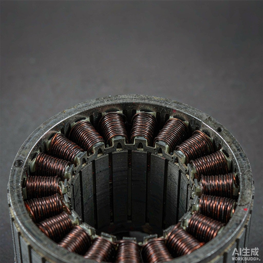
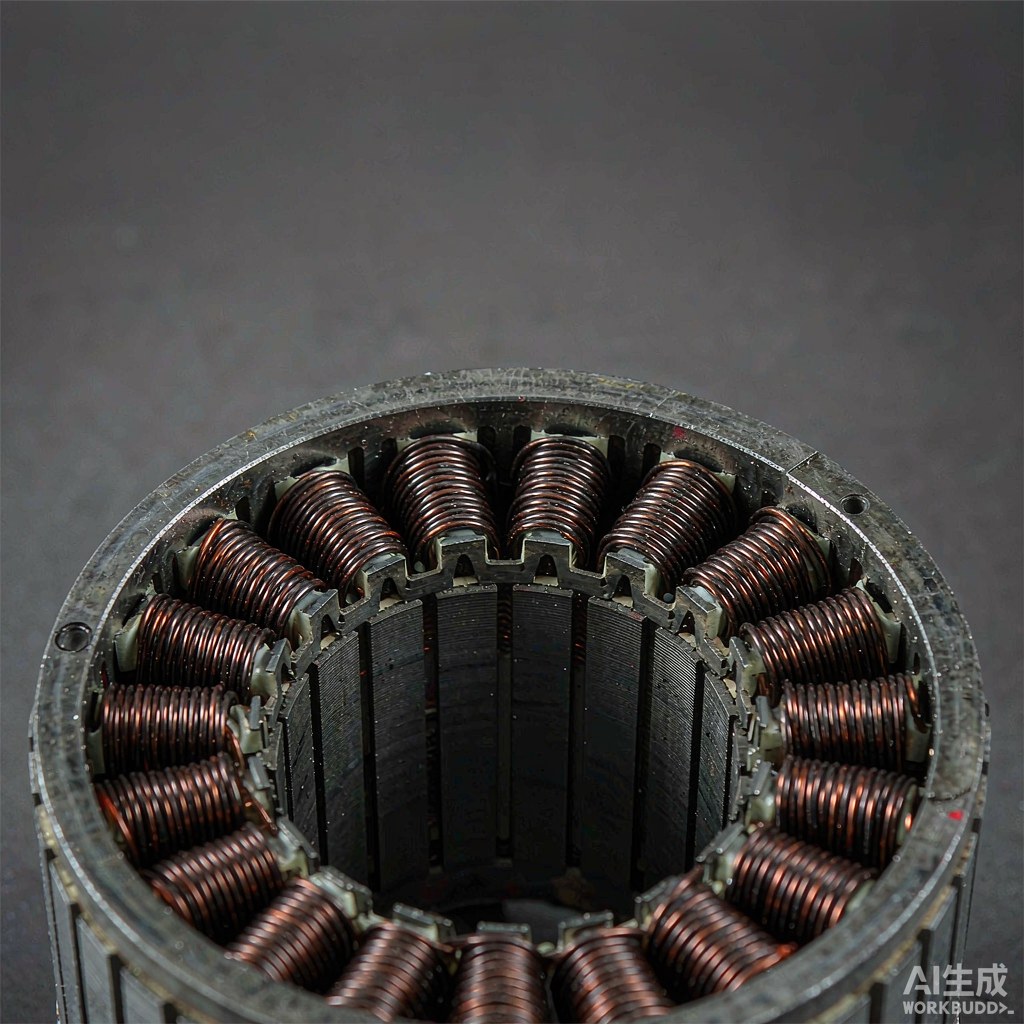
Fig. 1 - Repeated stator slots make small phase-to-phase differences visible in the winding. Illustrative image, AI-generated, not a product photograph.
Termination and connection consistency
A phase is not finished until its leads are terminated, and termination is a common source of difference. Lead length, joint resistance and routing add small series contributions. If one phase has a longer lead or a joint made with a different dwell, its resistance shifts even with an identical winding.
Connection topology matters too. Whether phases join in a star or a delta decides how a small asymmetry shows up at the terminals. A consistent termination method applied in the same sequence to every phase removes one variable. These are process-consistency controls; the electrical design belongs to the motor specification, not a winding program.
| Motor requirement | Winding implication | Measurement | Limit of the check |
|---|---|---|---|
| Balanced torque between phases | Equal turn count and mean turn length | Per-phase resistance at a common temperature | A snapshot, hides drift across lots |
| Repeatable holding position | Consistent slot fill and magnetic axis | Wound profile against a limit sample | Comparative, not an absolute tolerance |
| Even phase heating | Matched wire lot and tension per phase | Resistance spread between phases | Cannot identify which cause dominates |
| Stable end-turn envelope | Controlled traverse and reversal dwell | Visual profile and end-turn height | Describes conformance, not air-gap fit |
| Consistent terminal resistance | Identical lead length and joint method | Resistance measured at the terminals | Includes joint and lead, not coil alone |
| Predictable phase connection | Same join sequence and topology | Continuity and connection-map check | Electrical design, not a winding setting |
| Uniformity over production | Baseline retained for comparison | Trend of per-phase results over runs | Needs repeated samples to be meaningful |
Which measurements reveal a systematic difference
A systematic difference repeats in the same direction on successive parts; a random one does not. Per-phase resistance, turn count, wound profile and terminal resistance work best recorded as a set on the same article, since one metric rarely separates cause from symptom. Plotting each phase as its own trace, rather than averaging them, makes a phase-one-high, phase-two-low pattern visible.
Inductance and a low-voltage impedance balance reveal differences that resistance misses, but they are sensitive to rotor position, test frequency and fixture, so they demand a fixed setup. No bench measurement fully predicts in-service behaviour. A change in the measurement method can look exactly like a change in the winding.
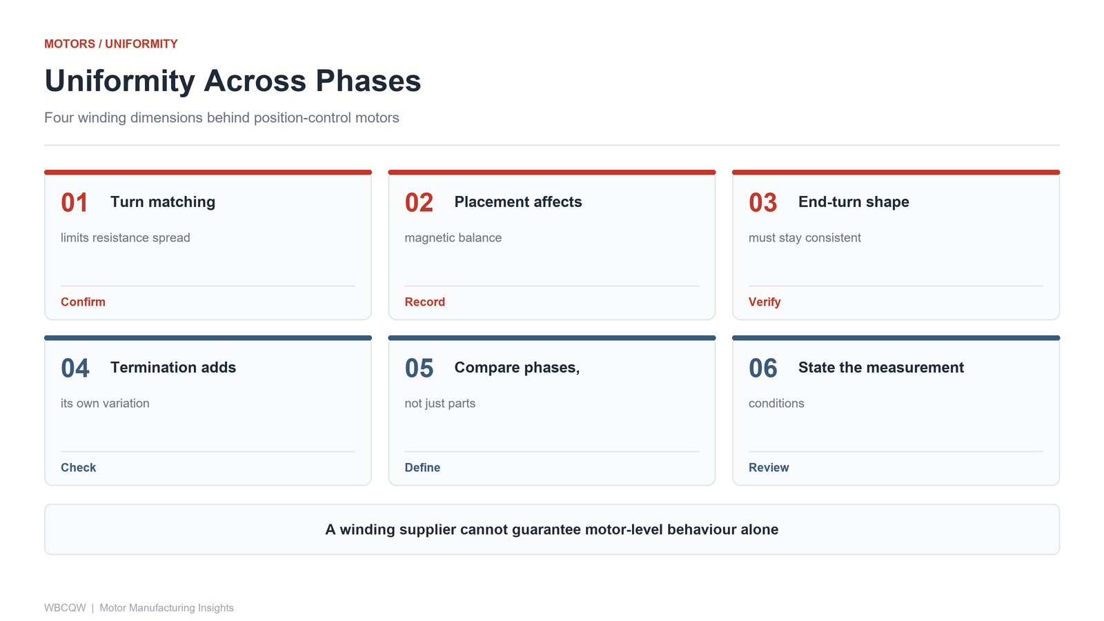
Fig. 2 - Four uniformity dimensions for stepper and servo stator windings. Illustrative diagram, not a product photograph.
Translating motor requirements into winding checks
The useful output is a short list mapping each motor-level concern to a winding parameter and a recorded measurement. Turn count, tension, traverse pitch, reversal dwell and termination sequence are the inputs; per-phase resistance, profile and connection checks are the outputs. Each entry should name the reference part, the test conditions and what counts as a difference worth investigating.
Keep the scope modest. A check sheet proves a set of parts was wound consistently under one set of conditions, on one wire lot, by one program. It does not prove capability across lots, shifts or machine wear, and it does not replace motor-level validation on a dynamometer. Uniformity is built from repeated runs against a controlled baseline, not a single article. The value of the checks is that a drift can be seen early and traced to a specific input.